Output
Scenes
Any nodes created during the import will be added to a new Assembly in the Scenes tree. The Assembly is named after the filename of the import. If the Import and Merge option was used, the name of the Assembly will consist of the "Merged" keyword, the filename of the import, and the date it was merged into the scene.
Libraries
Any geometry, texture or material nodes created during the import will be added to a new Library in the Libraries tree. The Library is named after the filename of the import (minus the extension).
Metadata
Metadata provides supplementary information about imported nodes. The importer reads any metadata stored in the imported file and adds it to relevant nodes as tables. Different groups of metadata will be added to separate attribute tables, using their group name – if available – or the generic metadata table name. If the metadata table is too long, it will be split into multiple tables for performance reasons.
 |  |
|---|
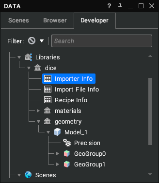
Importers generate 3 metadata tables of their own in the Libraries tree:
| Metadata | Description |
|---|---|
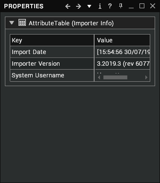
| Importer Info | Information about the importer that was used to import this file such as its version, date, etc. |
| Importer File Info | Information about the imported file such as its filename, date, etc. |
| Recipe Info | Information about the recipe file and importer settings used to import the file. |
Precision Data
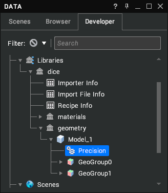
Precision data stores information about the tolerance values used to tessellate the different nodes in the import. It is parented to the Model node in the Libraries tree. Precision data will be available for importers that support it if the scene includes BREP data, since this is used to generate triangles in the scene and represent precision values. To generate precision data during the import process, Tessellation Read Mode must be set to kA3DreadGeomAndTess.
 |  |
|---|
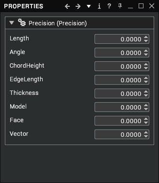
Precision data has the following properties:
| Property | Description |
|---|---|
| Length | Tolerance value used to ensure that extra vertices are not created too close to existing vertices. [default: 0.0] |
| Angle | The maximum angular deviation allowed between an analytical surface and its triangulation. Pairs of triangles cannot incorporate a dihedral angle greater than this value, which is expressed in degrees. This setting determines the minimum number of faces that may represent the circumference of a true cylinder, regardless of the Chord Height Tolerance setting. Medium and small objects relative to the total scene bounding box may easily fall within surface tolerance tessellation tolerances, with perhaps only four or five sides representing a true cylindrical surface. By using this tolerance setting you are controlling the “coarseness” of tessellation regardless of the geometry’s relative size in the scene. For instance, an angle of 30 results in a 12-sided tessellated cylinder, and an angle of 45 results in an 8-sided tessellated cylinder. [default: 0.0] |
| Chord Height | Tolerance value permitted between a surface described by the BREPs and the polygons that are produced by the tessellation process to approximate that surface. A smaller chord height causes more polygons to be produced, resulting in smoother models. [default: 0.0] |
| Edge Length | Smallest edge tolerance value. If edge length is smaller than this value, it will not be created. [default: 0.0] |
| Thickness | Smallest thickness of a face tolerance value. [default: 0.0] |
| Model | A general tolerance for the entire model (more specific tolerances override this value). [default: 0.0] |
| Face | The tolerance of points on a face of the model. [default: 0.0] |
| Vector | The tolerance of any vectors associated with the model. [default: 0.0] |
Simplified Representations
Some importers support simplified representations, which are extracted from the file with views. Each view includes visibility rules for nodes in the scene, alongside a camera location to set the viewpoint for the view. For each view in the scene, the importer creates a snapshot with the updated visibility rules for the scene nodes. It also creates a viewpoint node and adds it to the Viewpoints group in the scene.
The viewpoint is linked to the snapshot through a script added to an Activate Event in the snapshot event handler. This activates a Fly To operation on the linked viewpoint as soon as a new snapshot is applied.
To edit the viewpoint of an existing view snapshot you need to visit, edit and re-compile the snapshot event script.