Geometry Operators
The Geometry Operators provide a way to post-process meshes imported into Visionary Render. They are shown in the Properties window when the following node types are selected:
- Assembly
- Visual
- Library
- Model
- GeoGroup
- Mesh
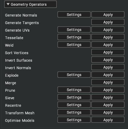
| Button | Description |
|---|---|
| Settings | Show configuration options for a geometry operator. The default values of these settings can be changed in Settings > Tools > Mesh. |
| Apply | Traverse down the tree from the selected node and apply a geometry operator to each mesh encountered. |
Generate Normals
The Generate Normals operator calculates the normal vectors for each vertex of a mesh.
- Smoothing Threshold [default: 55.0] – the smoothing threshold defines the threshold angle (in degrees) between polygonal edges after which the vertex normal will not be averaged with the surrounding normals. Modifying this angle can result in the faces being lit as individual surfaces, creating a faceted appearance to the mesh surface. An example of this can be seen below.
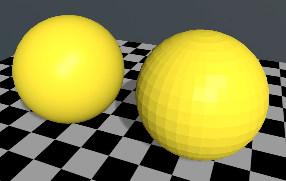
An example of the effect of the smoothing threshold setting on the ‘Generate Normals’ operator. The sphere on the left has a smoothing threshold of 35 degrees whilst the sphere on the right has a smoothing threshold of 5 degrees.
If the mesh has existing normals these will be replaced.
Generate Tangents
The Generate Tangents operator calculates the tangent vectors for each vertex on a mesh. For this operator to act, the mesh must have normals associated with it.
Generate UVs
The Generate UVs operator calculates texture coordinates for each vertex on a mesh. For a mesh to be texture mapped it must have texture (UV) coordinates associated with each vertex.
- Mapping Mode [default: Plane] – there are 5 types of mapping that can be applied when generating texture coordinates: Plane, Box, Cylinder, Sphere and Linear. Each mode tends to be suited to certain types of shape.
| Image | Description |
|---|---|
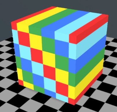 | Plane Generates texture coordinates by projecting a plane onto the mesh. |
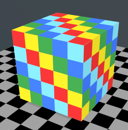 | Box Generates texture coordinates by projecting a cube onto the mesh. |
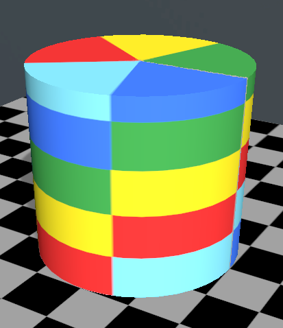 | Cylinder Generates texture coordinates by projecting a cylinder onto the mesh. |
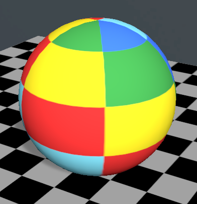 | Sphere Generates texture coordinates by projecting a sphere onto the mesh. |
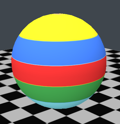 | Linear Generates texture coordinates by projecting a line onto the mesh. This can be used to apply gradient textures to geometry. |
- Mapping Axis [default: X] – the Mapping Axis setting allows you to specify which of the major axes (x, y, or z) the mapping shapes are orientated along. The images below show the effect that this has on various cubes.
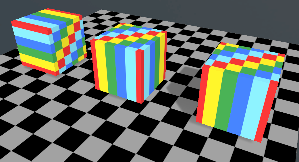
A cube with a Plane mapping orientated along the x, y, and z axes.
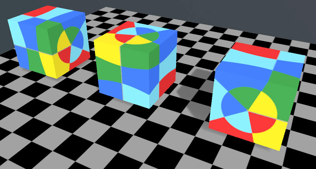
A cube with a Sphere mapping orientated along the x, y, and z axes.
- UV Offset [default: (0.0, 0.0)] – the UV offset parameter allows you to offset the texture coordinates from their default position. This can be used to adjust the position of textures on a mesh. An example of this setting being used in practice can be seen below.
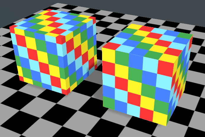
An example of two cubes with a Box mapped texture coordinates applied them. The left cube has no offset specified, whilst the right cube has an offset of 0.1 on the horizontal axis and 0.1 on the vertical.
- UV Scale [default: (1.0, 1.0)] – the UV scale parameter allows you to specify the size of the texture that is mapped to the mesh. If the WrapU and WrapV texture properties are set to GL_REPEAT and the scale of the texture is greater than 1, the texture will tile across the surfaces of the mesh. An example of this can be seen in the image below.
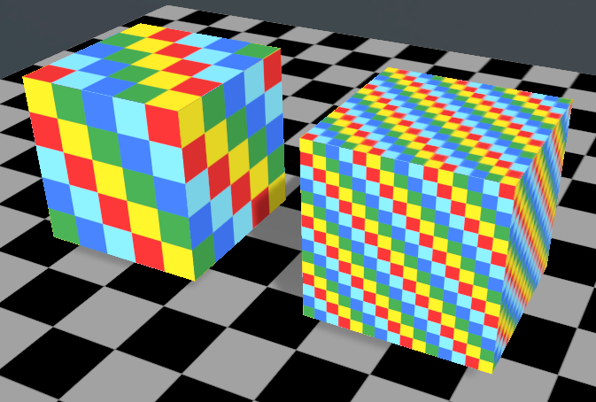
An example of two cubes with Box mapped texture coordinates applied to them. The left cube has a UV scale of 0, 0 applied, whilst the right has a UV scale of 3, 3 applied.
Tessellate
The Tessellate operator re-tessellates a selected mesh according to its Max Edge Length parameter. When modifying the mesh topology, the tessellate operator will interpolate and create all the vertex attributes associated with the mesh.
- Max Edge Length [default: 0.05] – specifies the maximum edge length of a polygon before it is split into a smaller triangle. An example of the tessellate operator acting on a coarsely meshed sphere can be seen below.
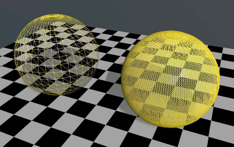
An example of the sphere that has been tessellated with the tessellate operator. The original sphere is shown on the left and the new sphere, tessellated with a Maximum Edge Length of 0.01, is shown on the right.
Weld
The Weld operator combines (or welds) vertices that are close to each other in a mesh. This operation can be useful when optimising the performance of a scene as it will reduce the number of vertices within the mesh.
Since the weld operation modifies the topology of the mesh, new normals should be generated after the operation has been performed.
- Tolerance [default: 0.003] – vertices within the specified tolerance value (in metres) will be combined. For best results and to prevent the weld operator being too destructive the value specified should be set to only include vertices that share polygonal edges. This value will vary from mesh to mesh.
Sort Vertices
The Sort Vertices operator optimises indexed triangle lists within a mesh to reduce the number of cache misses that occur when looking for vertices on the graphics card. This operation can provide significant performance gains when rendering large meshes. For best results, a weld operation should be performed as a prerequisite to this optimisation.
Invert Surfaces
The Invert Surfaces operator inverts the surfaces of a mesh by reversing the winding of the polygons. Since this operator invalidates the vertex normals it will automatically recalculate the normals until the operation has been completed.
Invert Normals
The Invert Normals operator inverts the direction of a mesh’s normals without affecting polygon winding order.
Explode
The Explode operator divides a mesh into individual nodes based on which parts of the mesh are connected.
- Tolerance [default: 0.003] – how much space can be between the mesh before it is identified as a separate component.
- Mode [default: Structure] – how the model is treated when performing the modifier.
- Structure – examine each node in the hierarchy separately, without considering that meshes from separate GeoGroups may be intersecting.
- Connected – examine the entire model as a single mesh. Allowing for smaller meshes, that are part of one big mesh, to not be needlessly separated. When this mode is selected, previous options are unavailable as they are not used as part of this option. Applying this option will explode the model into multiple models, based on what parts are attached. Any nodes referencing this model will be duplicated, to produce a node for each of the newly generated models. This action cannot be applied to models containing LODs.
- Explode Meshes [default: true] – tells the modifier that you wish to divide the mesh up into multiple meshes, based on what is connected. This produce a mesh for each separate component of the mesh, adding them to the tree as a sibling to the original.
- Explode GeoGroups [default: true] – tells the modifier to separate the model's meshes into their own geogroup nodes. This will result in each geogroup in the model containing a single unique mesh.
- Explode Models [default: true] – tells the modifier to separate the model's geogroups into their own model modes. This will result in each of the produced models only containing a single unique geogroup. As this divides a model into multiple models; any node that references the original model will be duplicated, to produce a node for each of the newly generated models. This action cannot be applied to models containing LODs.
Merge
The Merge operator merges all the children of a selected Assembly into a single Model node.
Prune
The Prune operator removes parts of the model based on which parts of the mesh are connected.
- Mode [default: Structure] –how the model is treated when performing the modifier.
- Structure – examine each mesh node independently. Not considering that separate mesh node may intersect.
- Connected – examine the entire model as a single mesh. Allowing for intersecting meshes to be treated as a single entity.
- Fraction [default: 0.1, range: (0.0, 1.0)] – the portion of the model that is to be pruned.
- Centre Bias [default: 0.0, range: (-2.0, 2.0)] – the bias applied when determining which parts of the model to remove. A negative value will try to remove mesh data from the edge of the model, whereas a positive value will try to remove mesh data from the centre of the model.
- Tolerance [default: 0.003] – how much space can be between the mesh before it is identified as a separate component.
Sieve
The Sieve operator removes parts of the model based on which parts of the mesh are connected and their overall size.
- Mode [default: Structure] – how the model is treated when performing the modifier.
- Structure – examine each mesh node independently. Not considering that separate mesh node may intersect.
- Connected – examine the entire model as a single mesh. Allowing for intersecting meshes to be treated as a single entity.
- Size Limit [default: 0.025] – the maximum size of what should be removed from the model. Models that have a dimension exceeding this value will be retained.
- Tolerance [default: 0.003] – how much space can be between the mesh before it is identified as a separate component.
Recentre
The Recentre operator recentres the mesh based on the values provided. Any assemblies that reference this mesh, if they are the first child visual, will have the inverse transform applied, to not impact the visual state of the scene.
- New Origin [default: (0.5, 0.5, 0.5)] – the desired centre point of the model. If relative the origin will be relative to the bounding box of the model, with (0.5, 0.5, 0.5) being the centre of the model. If not relative the origin will be an absolute position.
- Relative To Bounds [default: true] – (see above)
Transform Mesh
The Transform Mesh operator will transform the mesh vertex properties based on the values provided.
- Translation [default: (0.0, 0.0, 0.0)] – the displacement to be applied to the model.
- Rotation [default: (0.0, 0.0, 0.0)] – the rotation to be applied to the model.
- Scale [default: (1.0, 1.0, 1.0)] – the scale factor to be applied to the model.
- Transform Visuals [default: true] – tells the modifier that assemblies which reference this mesh, if they are the first child visual, will have the inverse transform applied, to not impact the visual state of the scene.
- Adjust Cull Face [default: true] – tells the modifier to invert the cull face of the model, in the case that the scale transform is negative.
Optimise Models
The Optimise Models operator permits various common optimisations to be automatically applied to your models.
- Merge GeoGroups [default: true] – some models can contain thousands of GeoGroups. This option merges all the GeoGroups that use the same material into a single GeoGroup. Models are unaffected by the merges and can be moved and copied as normal. The only time that it might not be desirable to merge meshes and GeoGroups is when they need to be copied, deleted, or moved within models.
- Vertex Sort [default: true] – this option orders the vertices in a mesh so that they are grouped according to use. This results in more efficient memory usage.
- Pack Meshes [default: true] – Each model is made up of one or more GeoGroups and each GeoGroup is made up of one or more meshes. When some models are imported they have many meshes in each GeoGroup. The worst case is when each triangle in a model has its own mesh. This can lead to hundreds – even thousands – of meshes in each GeoGroup. The problem with this is that that there is a certain overhead for processing each mesh. For a GeoGroup with many meshes the processing time can be much larger than the time to process the actual geometry in the meshes. This option packs your meshes into a far smaller number of meshes, thus removing any large overhead. It is particularly useful when each triangle of a GeoGroup has its own mesh.