Manipulators
PRS Manipulator
The PRS manipulator is a 3D widget that enables you to change the position, rotation, and scale of the selected object. It can be enabled from the Toolbar or by pressing F9.
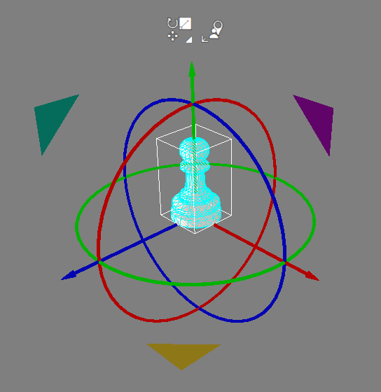
Once you have enabled the PRS manipulator, any selected assembly will be overlaid with the PRS widget. The image above shows a selected assembly and the PRS widget positioned at the centre of the Visual geometry. The alignment of the axes will default to the parent's coordinate system but can also be changed to world coordinates using the floating controls above the manipulator.
The red, green, and blue elements are associated with the X, Y, and Z axes. The cyan, magenta, and yellow elements refer to actions which are associated with two axes at once, as on a plane.
- Red represents the X axis.
- Green represents the Y axis.
- Blue represents the Z axis.
- Cyan represents the YZ plane.
- Magenta represents the YX plane.
- Yellow represents the XZ plane.
As the mouse moves over the PRS widget the different parts are highlighted in bright yellow. The two floating buttons above the PRS control the mode (Position only, Rotation only, Scale only), and coordinate system (World, Local, Parent).
| Image | Description |
|---|---|
| Position The image shows the elements of the PRS widget which represent the position manipulation. By left-clicking and dragging on the elements you can:
| |
| Rotation The image shows the rotation circles for each of the 3 axes. By left-clicking and dragging on the elements you can:
| |
| Scale The image shows the elements of the PRS widget which represent the scale manipulation. By left-clicking and dragging on the element you can:
|
Grid
| Image | Description |
|---|---|
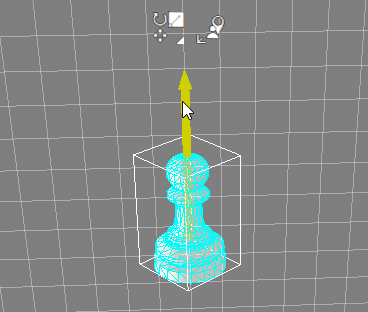 | When you click on part of the PRS widget Visionary Render can display a snap grid helper. If you click on a position or scale element, then you get a white grid appearing. This grid is created at a set spacing and restricts you to translating or scaling to that grid spacing. The setting for this grid can be changed in the Settings window under Tools > PRS Manipulator. This feature can be disabled by unchecking the Snapping checkbox. |
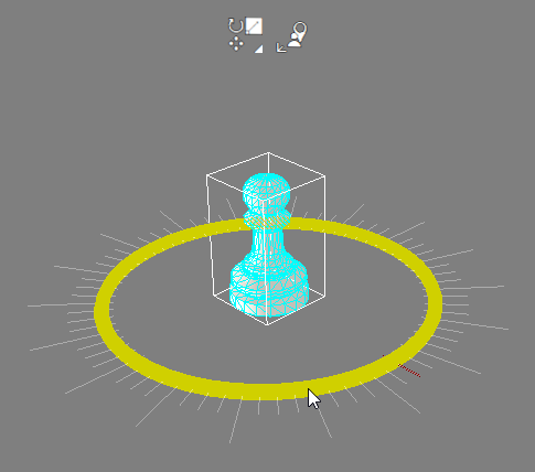 | If you clicked on a rotation element of the PRS then a set of radial snap points are created. The angle for these snap points is set in the Settings window under Tools > PRS Manipulator. This feature can be disabled by unchecking the Snapping checkbox. Using the mouse wheel while holding the left mouse button down over elements of the PRS manipulator will alter the snap size. |
Coordinate System
The coordinate system can be changed from the right-hand button above the PRS manipulator. There are 3 coordinate systems:
| Icon | Description |
|---|---|
| Local Transforms the object along its own local coordinate axis. | |
| World Transforms the object in the world coordinate axis. | |
| Parent Transforms the object in its parent’s world coordinate axis. |
Settings
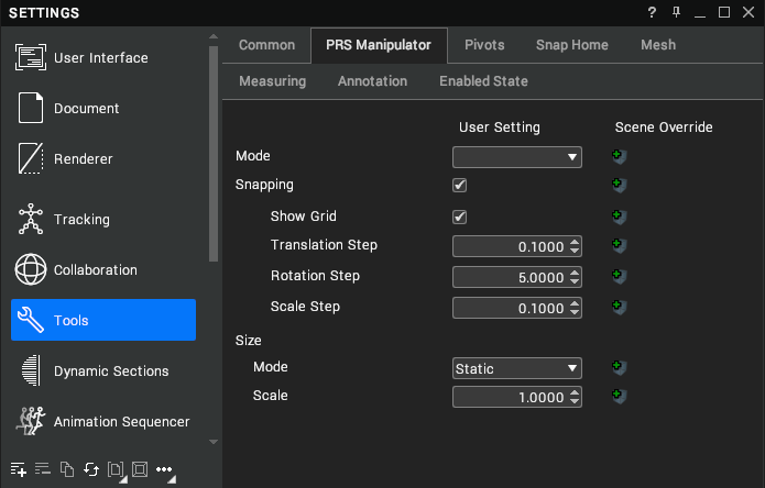
You can configure the PRS manipulator by opening the Settings window (F6) and navigating to Tools > PRS Manipulator.
| Setting | Description |
|---|---|
| Mode | Whether to move, rotate and scale objects at the same time. [default: Full Mode] |
| Snapping | Enable snapping to a grid during movement. [default: true] |
| Snapping > Show Grid | Render the snap grid and rotation lines. [default: true] |
| Snapping > Translation Step | The step size of the translation snapping grid. [default: 0.1] |
| Snapping > Rotation Step | The step size of the rotation snapping grid. [default: 5.0] |
| Snapping > Scale Step | The step size of the scale snapping grid. [default: 0.1] |
| Size > Mode | The method used to size the PRS manipulator. [default: Static] |
| Size > Mode > Scale Step | The distance the camera needs to move from the PRS manipulator before it is scaled in partially dynamic mode. [default: 0.5] |
| Size > Scale | The scale of the PRS manipulator. [default: 1.0] |
Mouse Manipulator
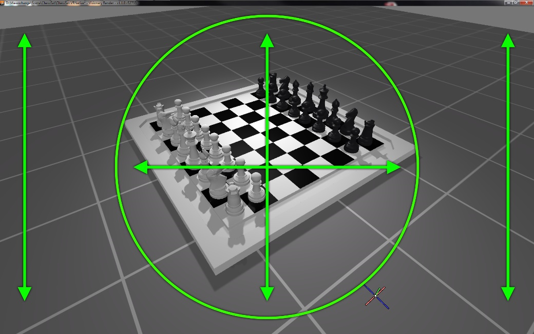
The mouse manipulator permits you to move and rotate Assemblies using a combination of mouse movement and key presses. It can be enabled or disabled from the Toolbar (it is enabled by default). The behaviour of the manipulator varies depending on whether the Assemblies are inside a circle at the centre of the screen, as in the image below.
| Action | Description |
|---|---|
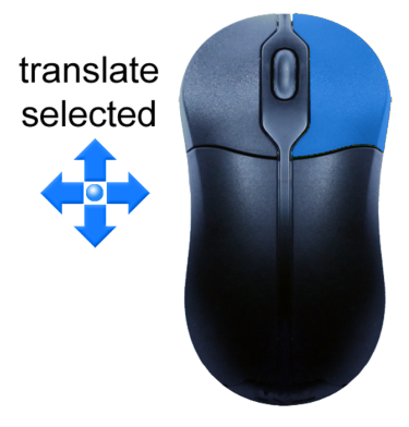 | Right-click and drag an Assembly in the 3D scene to translate it. If the Assembly is inside the circle, it will translate up, down, left or right. If the Assembly is outside the circle, it will translate towards or away from the camera. |
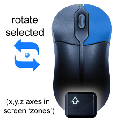 | Right-click and drag an Assembly in the 3D scene with Shift held down to rotate it. If the Assembly is inside the circle, it will rotate about all 3 axes. If the Assembly is outside the circle, it will rotate about a single axis. |
SpaceMouse Manipulator
If you have a 3D mouse product installed, it can be used to manipulate assemblies. The SpaceMouse manipulator can be enabled or disabled from the Toolbar. With assemblies selected in the 3D scene, hold Ctrl to transform the selection. All transforms are relative to the assembly's original transform.
- Push the 3D mouse forward and the assembly will move away from the view.
- Pull the 3D mouse backwards and the assembly will move towards from the view.
- Lift the 3D mouse up and the assembly will move up - in the screen coordinate system.
- Press the 3D mouse down and the assembly will move down - in the screen coordinate system.
- Push the 3D mouse left and the assembly will move left in the view.
- Push the 3D mouse right and the assembly will move right in the view.
- Tilt the 3D mouse forwards/backwards to rotate the assembly forwards and backwards.
- Rotate the 3D mouse to rotate the assembly in the Y axis - of the view coordinate.
- Roll the 3D mouse left and right to roll the assembly left and right in the view coordinate system.
You can then quickly release Ctrl and re-orient the view to a better position and orientation and begin to manipulate the selected assemblies again.
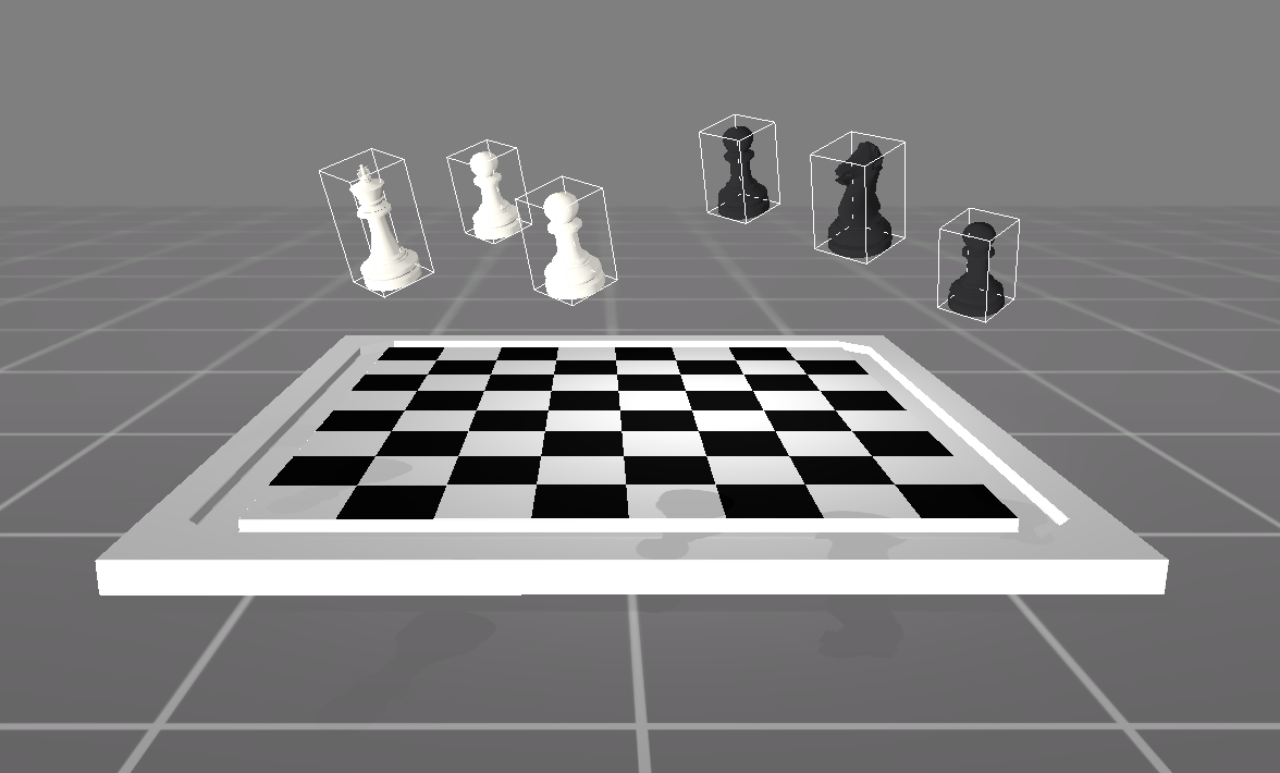
This works for multiple selected assemblies – the transform will still be relative to their original transform.