Measuring
The Measuring tool permits you to measure the distance between two points in your scene.
Basic Usage
Click the
icon in the Toolbar or press
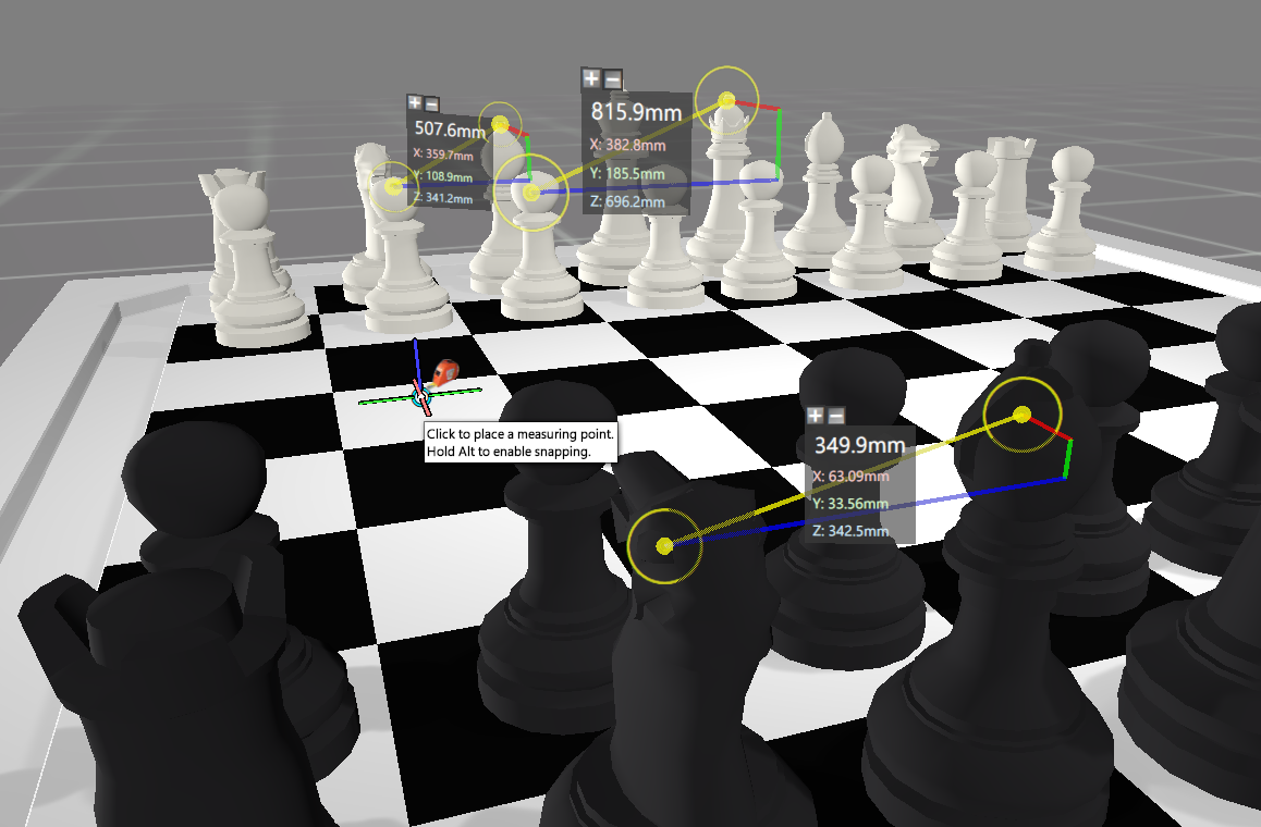
Ctrl+2to enable the Measuring Tool.The scene cursor should now show a measuring tape icon when hovered over some geometry.
Click on the point that you wish to measure from. A marker will be added to that location. If you need to adjust its position, click and drag the marker to move it.
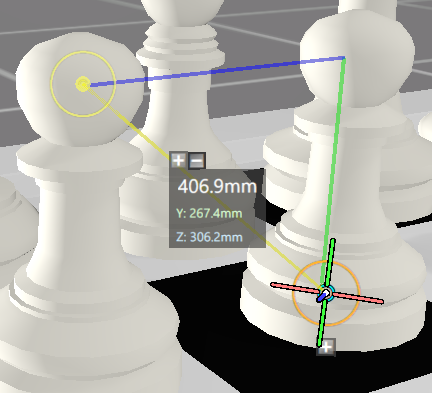
Now click on the point that you wish to measure to. A marker will be added to that location and a GUI will appear. The number in white (406.9mm) is the straight-line distance between the two points. (Tip: to add additional measurements, hold Shift and click on some other geometry.)
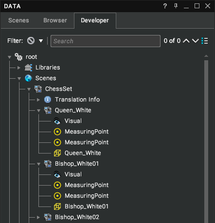
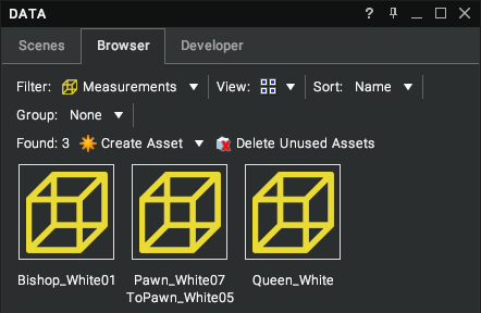
The measuring points will appear in the Scenes or Developer tree beneath the nodes they are attached to. They can also be shown in the Browser via the Measurements filter.
Dimension
A dimension represents the distance between measuring points – each pair of measuring points will have an associated dimension.
Scene GUI
For each dimension, Visionary Render displays details of the dimension as a 3D GUI.
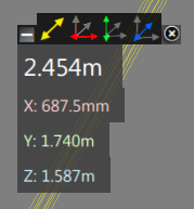
The image shows the 3D GUI. The top row of icons indicates which distances should be displayed on the GUI.
| Image | Description |
|---|---|
| Show or hide straight-line distance. | |
| Show or hide X distance. | |
| Show or hide Y distance. | |
| Show or hide Z distance. |
Clicking on the actual distance value toggles whether the display is locked visible or not. If locked visible, then that distance value will remain visible all the time. If unlocked then each individual distance will only be visible when their value is higher than a pre-set ratio of the other distances, this is controlled by the Snap Angle setting. The four distances on the image below are all locked and will be displayed all the time.
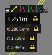
The units used within the display are evaluated on the scale of each distance.
Example
| Image | Description |
|---|---|
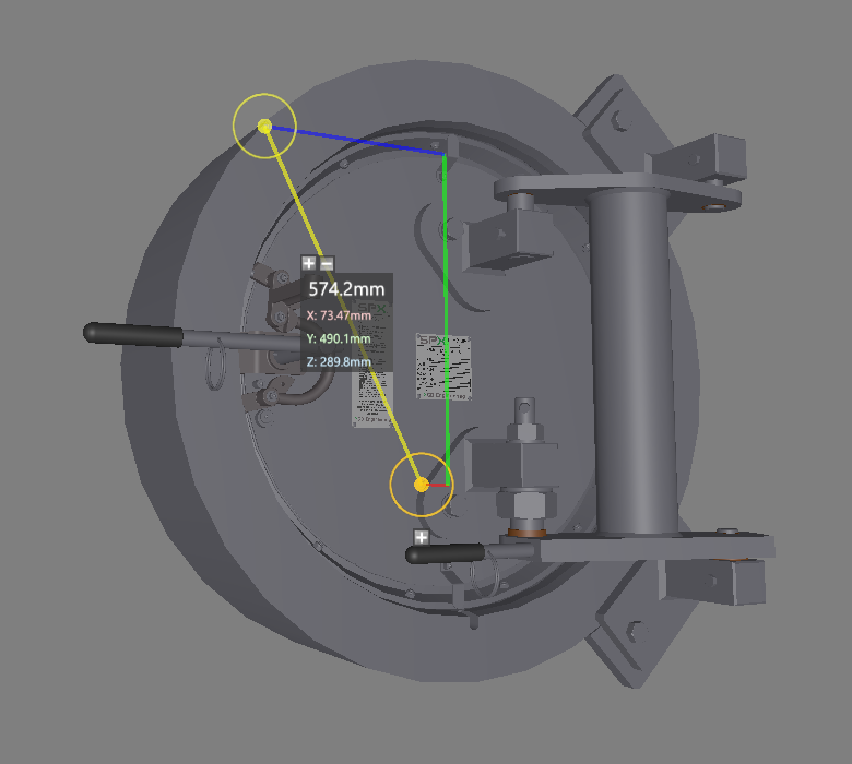 | The image shows a simple example of a dimension. Both the black and white pawns have a measuring point attached to them. The direct distance between them is shown as a yellow line, with the axial distances being shown as green red and blue lines. The numerical display in the centre of the yellow line is a display of the 4 distances – direct, X, Y and Z. This display will rotate to face you and update when either the assemblies are move or the measuring points themselves. |
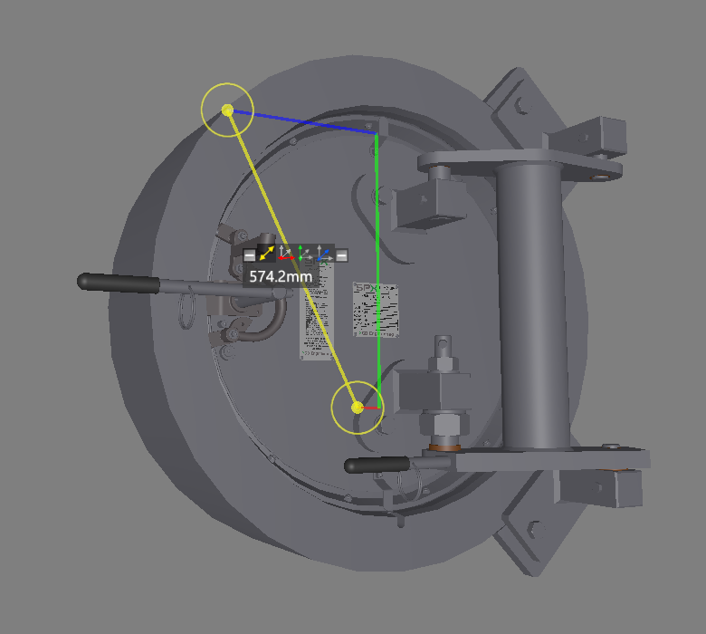 | The same measurement can be changed to display the coordinates of each of the measuring points. You can also remove the X, Y, Z numerical and line displays to simplify the display. You can select and drag either of the two measuring points around the scene. If you drag the point onto part of the screen with no assemblies, then it will remain at the last valid location. The measuring points also have a display which can show the position of the point or the range of movement in each axis over the lifetime of the point. |
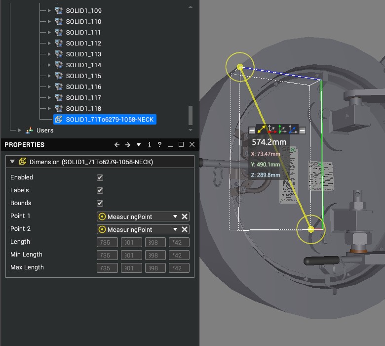 | This is the same dimension from a different angle. This time it shows the bounding box of the dimension. This is enabled in the properties window for the dimension. The red, green, and blue lines are drawn from a different position but show the same distances. The line of icons above the distance is a simple enable/disable of each of the distances. |
Browser
Dimensions can be shown in the Browser by selecting Measurements from the Filter drop-down. The list view shows the parent, length, and XYZ distances of each dimension.
Delete
To delete a dimension, select it in the scene and press the Delete key or right-click and select Delete from the context menu. It can also be deleted from the Tree View or Browser.
Measuring Point
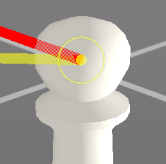
A measuring point is a single position (x, y, z) in the scene that is attached to a piece of geometry. It is displayed in the scene with a marker.
Scene GUI
You can display the absolute position of a measuring point and its range of movement since it was created.
Hover the cursor over a measuring point and click on it to select it. Once selected, the measuring point will be highlighted orange and a
+icon will appear below it. (Alternatively, you can select the measuring point in the tree view.)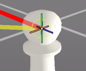
Click on the
+icon to show the menu.A menu will appear with 3 options: Coords, Range and Reset Range. To hide this menu again, click the
-icon.
Coords
Click the Coords menu option to show the x, y, and z position of the measuring point in the scene. Click the option again to hide the display.
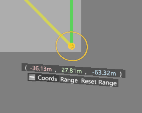
Range
Click the Range menu option to show the distance travelled by the measuring point in the x, y, and z axes from its initial position.
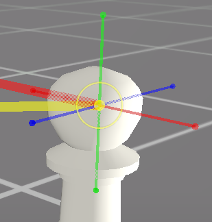
The distance travelled is computed when the parent object that the measuring point is attached to is moved, not the measuring point itself.
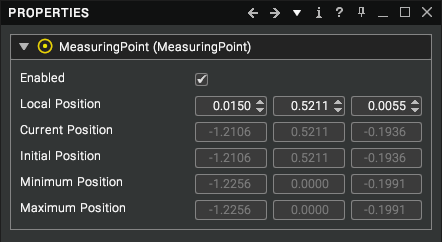
The initial, minimum, and maximum positions are shown in the Properties window when the measuring point is selected.
Reset Range
Click the Reset Range menu option to set the initial position of the measuring point to its current position. The visual in the scene that shows the distance travelled will now be hidden until the parent object is moved again.
Snap To Vertex
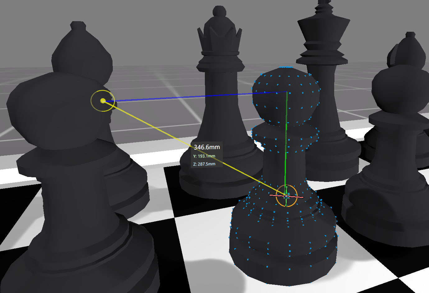
Measuring points can be snapped to the vertices of geometry when they are dragged. To do this, hold down Alt whilst dragging a measuring point. The vertices of the model that the measuring point is attached to will be highlighted as below.
Delete
To delete a measuring point, select it in the scene and press the Delete key or right-click and select Delete from the context menu. It can also be deleted from the Tree View.
The measuring point will be deleted if its parent object is deleted.
Settings
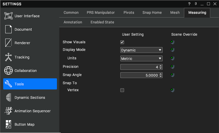
To configure the Measuring Tool, open the Settings window (F6) and select Tools > Measuring.
| Setting | Description |
|---|---|
| Show Visuals | Show or hide all measuring points and their GUI’s in the scene. [default: true] |
| Display Mode |
|
| Display Mode > Units | (This setting is shown when the Display Mode is set to Dynamic.)
|
| Display Mode > Base Unit | (This setting is shown when the Display Mode is set to Base Unit.) A single unit to show measurements in. There are 8 options:
|
| Precision | The number of significant figures to show for each measurement value. [default: 4] |
| Snap Angle | The maximum angle in degrees at which a measurement is treated as if it is aligned to an axis (i.e. that axis will be hidden from the GUI). [default: 5.0] |
| Snap To Vertex | By default, snapping only occurs when the Alt key is held down whilst dragging a measuring point. To enable it without having to press Alt, click Tools > Measuring > Snap To > Vertex in the Settings window. Pressing Alt will now disable snapping instead. The colour and size of the vertex markers can be configured from the Settings window under User Interface > Mouse > Snap. [default: false] 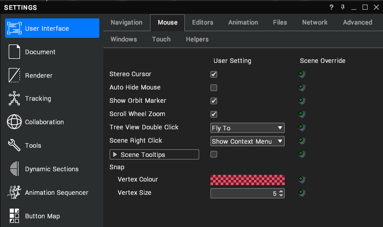 |