Augmented Reality
Visionary Render supports Augmented Reality (AR) via headsets such as the HoloLens 2. This section will guide you through the process of setting up a scene for AR usage with the HoloLens 2, which provides tracking via QR codes.

Tracking
Scene
You can use a single QR code to locate your virtual scene in the real world.
Load/import the 3D model that you want to use in AR.
Enable helpers using the toolbar or the Settings window (User Interface > Helpers > Helper Visibility Mode). Also ensure that the AR Helpers category is enabled by right-clicking on the toolbar button or checking the Show AR Helpers setting.
In the Developer tree view, right-click on the Scenes node and choose Create > View/Tracking Nodes > AR Marker. A QR code helper and small white sphere will appear.
Enable the PRS Manipulator and move the helper to a known position and orientation in the scene. When placing the marker on a vertical surface, keep the Y (green) axis pointing upwards.
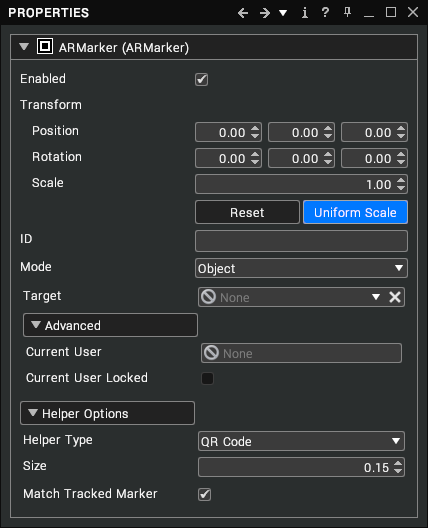
In the Properties window, enter a name in the ID property of the ARMarker node. This can be any text and/or number, but it's best to avoid long names as these will produce more complex QR codes that are harder for the headset to identify.
Right-click on the ARMarker node in the tree view and choose "Generate QR code" from the menu. This will show a file browser allowing you to save an image of the generated QR code. The default image format is PNG as it is widely supported but you can also choose SVG format to generate a vector image that will scale more cleanly up to large sizes.
Print the generated QR code. It is recommended to print at a reasonably large size, e.g. at least 20cm (8 inches), so that the headset can identify the QR code from a distance.
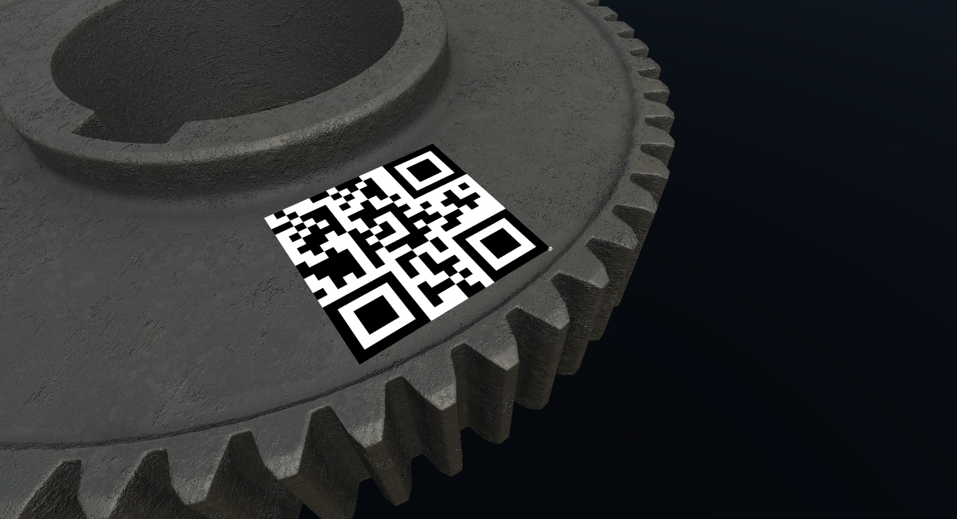
Attach the printed QR code to the real-world location matching the location chosen in step 4. Note that the orientation is important - the corner without a large square is the bottom-right. The top-left corner is the origin of the QR code and corresponds to the position of the ARMarker node in the Visionary Render scene. The top edge of the QR code is aligned to the X axis in Visionary Render. The image below shows the correct orientation for a QR code.
When using AR in a large space, you can add multiple AR markers at different locations for better accuracy. Visionary Render will use the one most recently detected by the headset to control the camera.
Object
You can also attach markers to moveable objects within a scene. You should setup at least one marker to locate the scene as a whole, as discussed, before adding markers to moveable objects. This is essential when using multiple HoloLenses in collaboration to ensure everyone is working in the same space.
Firstly, you need to create the AR marker. There are two ways to do this:
In the Developer tree view, right-click on the object's Assembly node and choose Create > View/Tracking Nodes > AR Marker.
Move the marker in the scene onto the surface of the object that you want to track.
In the Properties window, enter a unique ID for the ARMarker.
Change the ARMarker's Mode to "Object", then drag and drop the root assembly of the moveable object into the Target property.
OR
In the Developer tree view, right-click on the Scenes node and choose Create > View/Tracking Nodes > AR Marker.
In the Properties window, enter a unique ID for the ARMarker.
Change the ARMarker's Mode to "Object", then reparent the root assembly of the moveable object to the ARMarker.
Move the object in the scene to where the marker is located.
Finally, to set up the QR code:
Right-click on the ARMarker node in the tree view and choose "Generate QR code" from the menu. Save and print the generated image as described above.
Attach the printed QR code to the object. Note that a HoloLens expects the QR code to be on a flat surface and may struggle to track a QR code on a curve.
Enable AR marker tracking. When the QR code is detected by the headset, the object will be moved so that the virtual marker aligns with the real-world QR code.
HoloLens 2
To view your scene in the HoloLens 2:
Enable the HoloLens desktop immersion mode (see HoloLens 2).
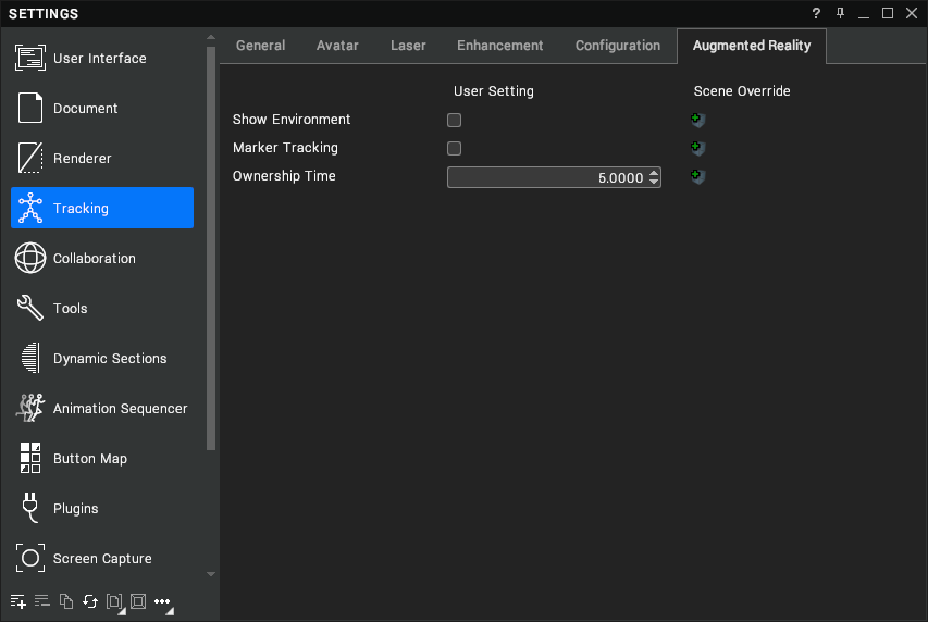
Enable AR marker tracking using the toolbar (in the Tracking group/rollout) or the Settings window (Tracking > Augmented Reality > Marker Tracking).
Put the headset on and look at a physical QR code. Once recognised by the headset, you should see a blue square containing the content of the QR code overlaid on the physical QR code. If a matching ARMarker node is found in the Visionary Render scene, your camera will be automatically positioned so that the virtual marker aligns with the real-world marker. Note that this means it is not possible to move the camera using the navigator tools while AR marker tracking is in use. Also note that Visionary Render will avoid pitching or rolling the camera, keeping the world upright regardless of the rotation of the QR code.
If necessary, adjust the position or orientation of the ARMarker node to fine-tune the alignment of the real and virtual worlds.
Tips
- Using only numbers, uppercase letters, spaces and the symbols
$%*+-./in an ARMarker's ID property will allow the QR code to use a more efficient encoding mode, allowing longer names to be encoded into a smaller QR code and/or better error correction. Using IDs of around 10 characters or less will allow the smallest QR code size to be used along with a good level of error correction. - The QR codes will be repeatedly detected by the HoloLens when in view, resulting in slight adjustments in their positioning, so you may wish to disable AR marker tracking once the scene has been located correctly.
- The QR code visuals can be disabled by turning off AR marker helpers from the Toolbar or Settings window.
AR Markers
Diagnostics
The Tracking tab of the Diagnostics window shows a table with all of the AR markers in your scene and/or detected by your headset.

If you have a printed QR code and want to quickly add a corresponding ARMarker node to a new scene, scan it with the headset then click the "Add to scene" button in the table.
Click on an ARMarker in the table to select it in the treeview and scene.
Properties

| Property | Description |
|---|---|
| Enabled | Whether or not the marker is enabled and visible in the 3D scene. [default: true] |
| Transform | Determines the position, rotation and scale of the marker. Select Reset to reset the position, rotation and scale to their default values. Select Uniform Scale to control whether the scale values in the X, Y and Z directions are edited as a single value or independently. [default: identity] |
| ID | A unique name that is used to generate and recognise a marker such as a QR code. [default: empty] |
| Mode | There are 2 options:
|
| Target | (Object Mode only) The root assembly containing this AR Marker, which will be moved in order to align the virtual marker with the real-world marker. [default: none] |
| Current User | (Object Mode only; Read-only) The user currently controlling the target object. [default: none] |
| Current User Locked | (Object Mode only; Read-only) Stops ownership of the target object from being changed. [default: false] |
| Helper Type | The style of the visual helper for this marker (does not affect detection of markers). There are 2 options:
|
| Size | The size of the visual helper for this marker (does not affect detection of markers). [default: 0.15] |
| Match Tracked Marker | Whether to update the helper type and size when the corresponding marker is detected in the real world. [default: true] |
Reverse Connection Mode
The Hololens has a reverse connection mode that permits you to connect to your machine from the HoloLens.
Setup
Start Visionary Render and enable HoloLens mode.
Press the Settings button in the HoloLens connection status window.
In the settings window, change HoloLens Connection Mode to Listen. (Leave the HoloLens Listen IP box empty unless you experience problems due to your PC being connected to multiple networks.)
Press the Generate QR code button in the HoloLens connection status window. This will generate a QR code containing ms-holographic-remoting://HOSTNAME where HOSTNAME is the name of your PC. Save and print the image.
Put on the HoloLens and look at the printed QR code. You don’t need to start the Holographic Remote app first (but it will also work if you do).
Either push the virtual button that appears or say “connect”.
The HoloLens will now attempt to connect to the PC running Visionary Render.
Troubleshooting
- The firewall on the PC may need to be configured to allow incoming connections on ports 8265 and 8266.
- If the HoloLens cannot resolve the host name of the PC, you could try using its IP address instead. Generate a QR code containing ms-holographic-remoting://x.x.x.x where x.x.x.x is the IP address of the PC. The Generate QR code button doesn’t have an option for IP addresses yet but there are 3 alternatives:
- Put the link in the ID property of an ARMarker node and generate a QR code from the context menu.
- Use the vrGenerateQRCodeFile Lua function (see the programming guide for more details).
- Use a third-party QR code generator.
- If the PC has multiple network adapters, you may need to specify which address to listen for connections on. You can see the list of local IP addresses in the Statistics section of the Network window after enabling networking. Determine which one is on the same network as the HoloLens and enter that into the HoloLens Listen IP setting.
- If you leave the Holographic Remoting app on the HoloLens and go back into it, it may still be trying to connect to the same address as before. If you need to revert to the normal connection mode, go to the home screen, find the Holographic Remoting cube, press ..., press X to close it, and then start it again.
Passthrough
The HoloLens supports passthrough, which permits you to view the real world around you whilst still viewing your hologram.
Setup
In the Oculus desktop app, go to Settings/Beta and enable “Developer runtime features” and “Pass-through over Oculus Link”.
Start Quest Link on your headset.
Start Visionary Render and switch to OpenXR mode.
Load a scene or create some geometry.
Go to Settings/Tracking/Augmented Reality and enable Show Environment. The real world should be visible in your headset instead of the scene background/sky.
Adjust the Background Opacity setting. This should blend smoothly between the real world and the scene background/sky.
Settings
Augmented Reality
![]()
| Setting | Description |
|---|---|
| Show Environment | Controls visibility of the real world when using a headset that supports video passthrough. [default: false] |
| Background Opacity | Controls the opacity of the scene background/sky when using a headset with a transparent display or video passthrough. [default: 0.0] |
| Marker Tracking | Enables tracking of AR markers such as QR codes, if supported by the current tracking mode and hardware. [default: false] |
| Ownership Time | The number of seconds that a user keeps exclusive control of an object linked to an AR marker after the marker is detected by their headset. [default: 5.0] |
HoloLens 2
There are some additional settings for the HoloLens tracking configuration mode.

| Setting | Description |
|---|---|
| HoloLens IP | The IP address of the HoloLens device. This is displayed when the HoloLens Remoting Player is running. [default: empty] |
| Hand Tracking | Enables tracking of the user's hands. [default: true] |
| Gesture Control | Enables pointing and selection using a pinch gesture. [default: true] |
| Avatar | The avatar file to load. [default: avatar_virtalis] |