Point Clouds
Visionary Render can render point clouds from any commercial software that can output point clouds as delimited text files (such as CSV, PTS or TXT files).
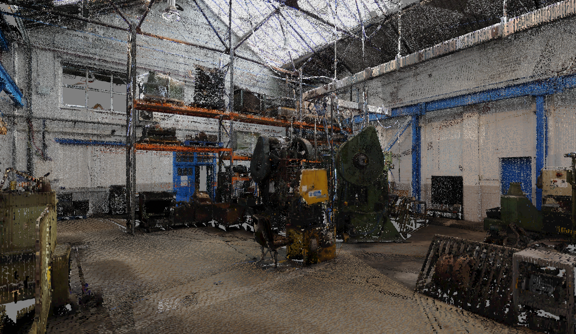
Suitable row formats are:
- X, Y, Z
- X, Y, Z, Intensity
- X, Y, Z, R, G, B
The R, G, B and Intensity values need to be in the range 0.0 to 1.0 or 0 to 255.
Converter
The point cloud converter translates delimited text files to a format that can be imported into Visionary Render’s point cloud renderer. It is a separate application that is included in the Visionary Render install package and can be found in the Visionary Render directory in the Start Menu.
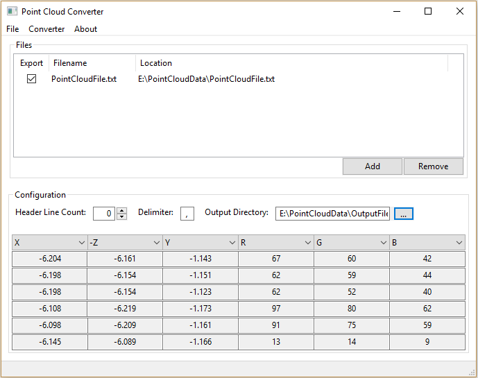
It only displays data contained within the first file in the list.
The converter doesn’t make any changes to the source files.
Add
To add a file, click on the Add button in the Files panel and browse to the directory that contains the ASCII files you want to import. Typical file extensions for point cloud files include CSV, PTS, TXT and XYZ.
A file dialog will be shown as below.
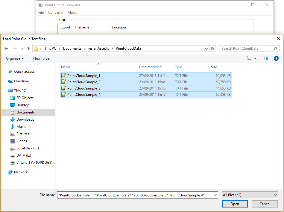
A warning dialog will be shown if the file doesn’t seem to contain any valid point cloud data. You can then choose to continue with the import by selecting Yes or cancel it by selecting No.
Remove
To remove a file, select the file in the files list and click on the Remove button. Hold down the Ctrl key to select multiple files to remove.

Configure
Customising the configuration settings allows you to tell the converter how to interpret the data or allows you to correct any mistakes made during the import.
Header Line Count
If your source data file contains some header information, you can use the Header Line Count edit box to specify how many lines of header information your file has.
Delimiter
The delimiter can be changed by typing in a new single character to the textbox. Input to this text box is limited to special characters only.
In most cases, the delimiter will be automatically detected. If not, then the example lines shown in the grid in the Configuration GUI will not appear as expected.
Data Field Interpretation
This tells the converter what type a field is, with the type being either a point in a 3D space or a colour. The fields types are:
- X Coordinate
- -X Coordinate
- Y Coordinate
- -Y Coordinate
- Z Coordinate
- -Z Coordinate
- R – Red colour component
- G – Green colour component
- B – Blue colour component
- Grey – Grey colour component
- None – Ignored
The converter sets a default assignment of X -Z Y R G B or X -Z Y None R G B if there are 7 fields. There can only be one assignment of each coordinate or colour component, but there can be multiple ‘None’ fields. Fields can be assigned by selecting one of the options from the combo box located at the top of each column in the data grid.
Output Directory
To specify a desired directory for the export file, click on the “…” output directory button and navigate to a folder and specify a filename.
Run
To run the converter, ensure an output directory has been specified then locate and click the Converter menu option located at the top of the application. Select Run from the drop down.
When the converter is running you will be presented with a progress dialog. If you wish to cancel the conversion operation either close the dialog or press the Cancel button. When the converter has finished the progress dialog will disappear.
Import
Once your data is converted, open Visionary Render and create an Assembly.
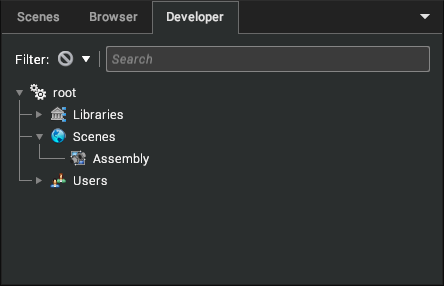
Switch to the Developer tab and select the newly created Assembly. Right-click and select Create > Point Cloud from the context menu. Select the filename in the Properties window and adjust the Brightness, Point Size, LOD scale as required.
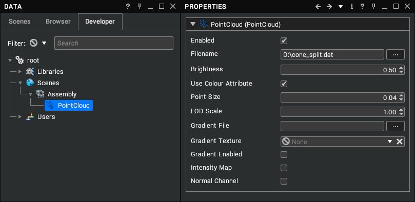
When used in a networked environment (Collaboration/Clustering) all machines must be able to access the Point Cloud file via a UNC network share, additionally when Clustered there will be periods when the cluster members are not showing similar data as the Point Cloud is streamed on demand.
One method to help with this is to copy the file locally to each PC in the collaboration ensuring each uses the same path. Because of the continuously varying field of view the level of detail algorithm used for the Point Cloud will not yield best results when using head tracking. Depending on the original data, you can colour the points in 3 different ways:
| Screenshot | Description |
|---|---|
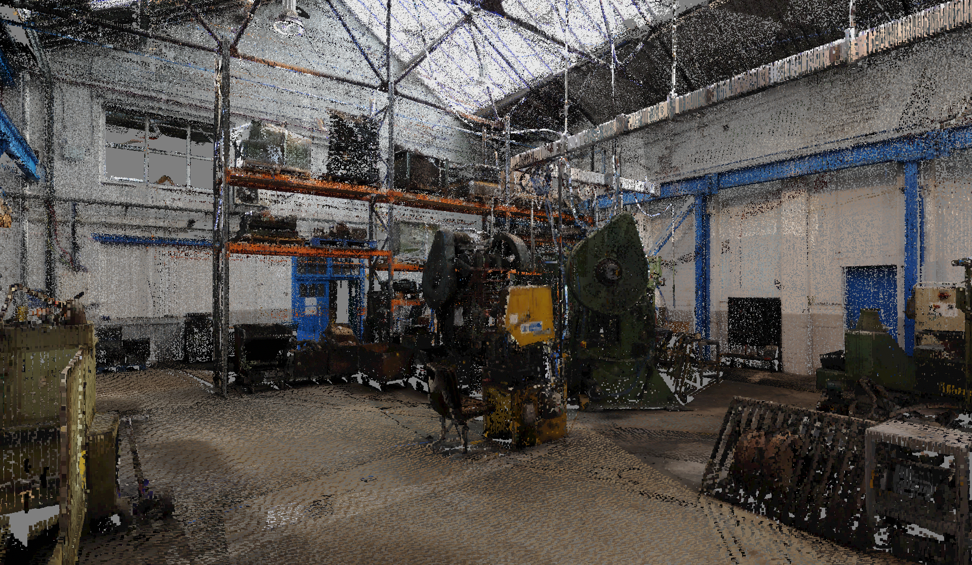 | Original file has red, green, and blue values for each point. |
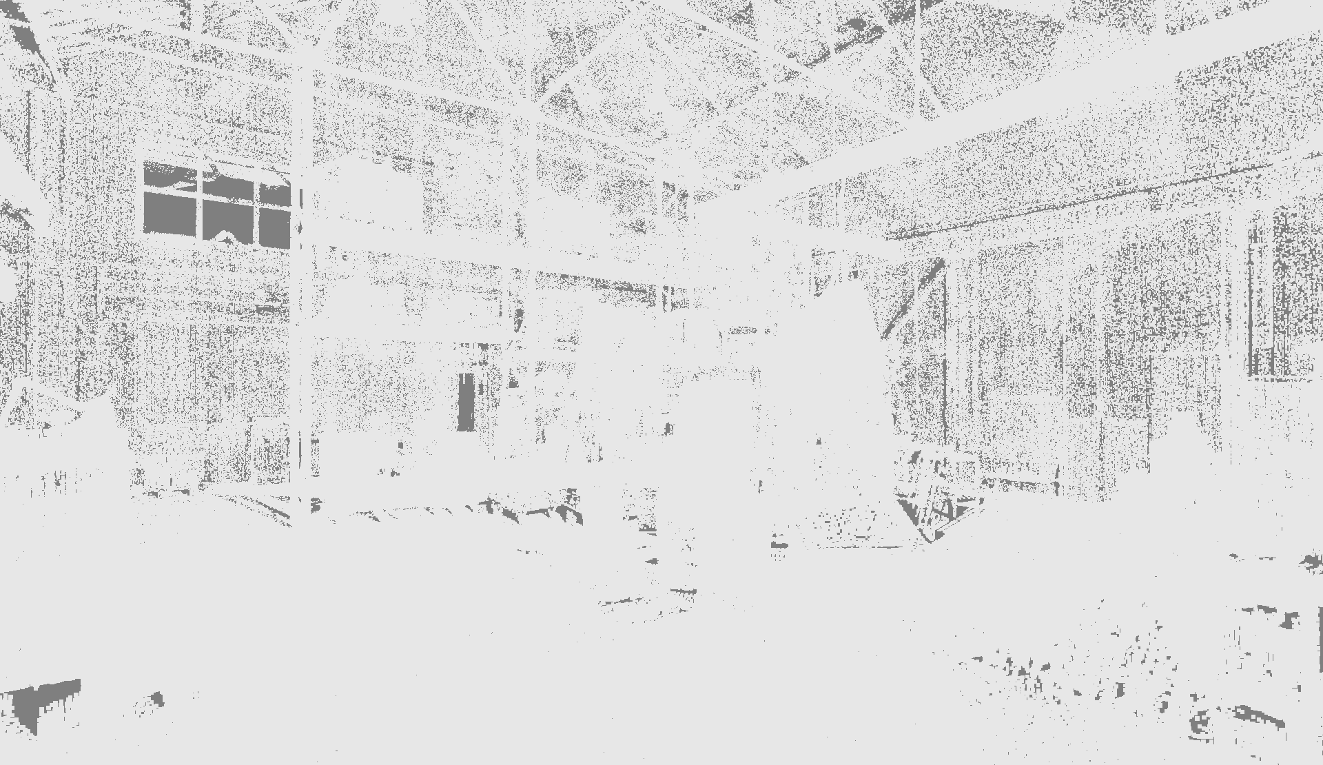 | Display the point cloud with no colour – disabling the Use Colour Attribute. |
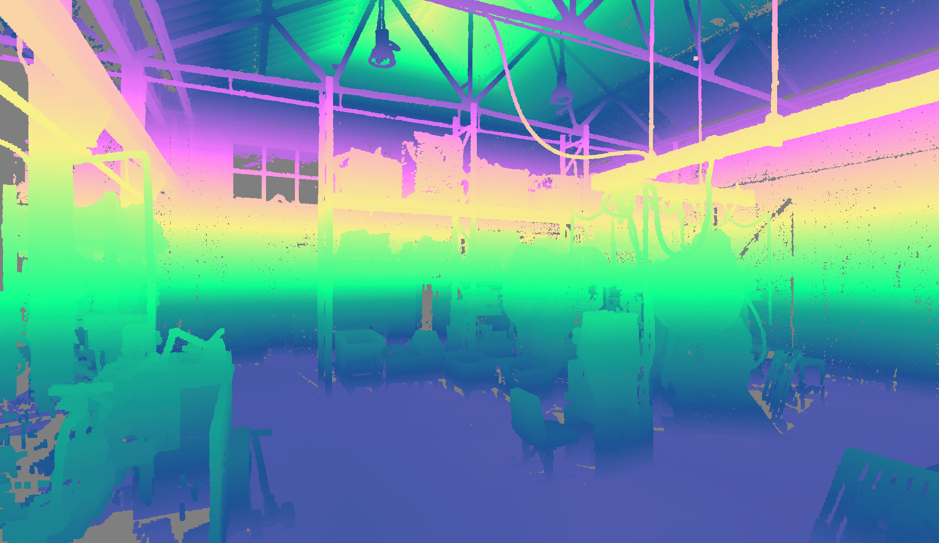 | Using a Gradient image to colour the points depending on their altitude. |
Edit
Properties
| Property | Description |
|---|---|
| Enabled | Toggles whether the Point Cloud is enabled and therefore visible and pickable in the 3D scene. [default: true] |
| Filename | Filename of the converted point cloud file. [default: none] |
| Brightness | Adjusts the brightness of the Point Cloud points, 0.0 is black, 0.5 is the original brightness, 1.0 is maximum brightness. [default: 0.5] |
| Use Colour Attribute | When enabled the Point Cloud colours are rendered (the colour from the original scan), otherwise the gradient or white. [default: true] |
| Point Size | Controls how large each point appears on the screen. This also controls how large the point is when calculating intersections with the Point Cloud whilst picking. [default: 0.04] |
| LOD Scale | Adjusts the LOD calculation so more or less detail is visible from a distance. For a fixed camera position a LOD scale of 2.0 draws approximately half the detail of LOD scale 1.0 and 0.5 twice the detail, 3.0 draws 4 times less detail and 0.25 4 times more detail.The larger the scale the fewer points are drawn, the smaller the scale the greater the number of points being drawn. [default: 1.0] |
| Gradient File | Filename of an image to supply gradient colours. [default: none] |
| Gradient Texture | A link to a Gradient or Texture used to supply gradient colours. [default: none] |
| Gradient Enabled | Controls whether the gradient is used to colour the points. [default: false] |
| Intensity Map | When enabled the gradient is applied to the Point Cloud by mapping the value of the point colour red channel otherwise the point altitude is used. [default: false] |
| Normal Channel | When Enabled the Point Cloud is rendered using a pseudo lighting algorithm. The surface angle for each pixel is calculated by reading the depth of the neighbouring pixels. To achieve a satisfactory result, the Point Cloud must have enough density and point size for the points to overlap. [default: false] |
| Alpha Threshold | Controls the visibility of points based on their alpha values – only points with alpha values greater than or equal to the threshold are rendered. When used in conjunction with a gradient, the alpha values are taken from the gradient, meaning that detailed control over the visibility of one or more ranges of values can be achieved using the Gradient Editor. [default: 0.0] |
Dynamic Sections
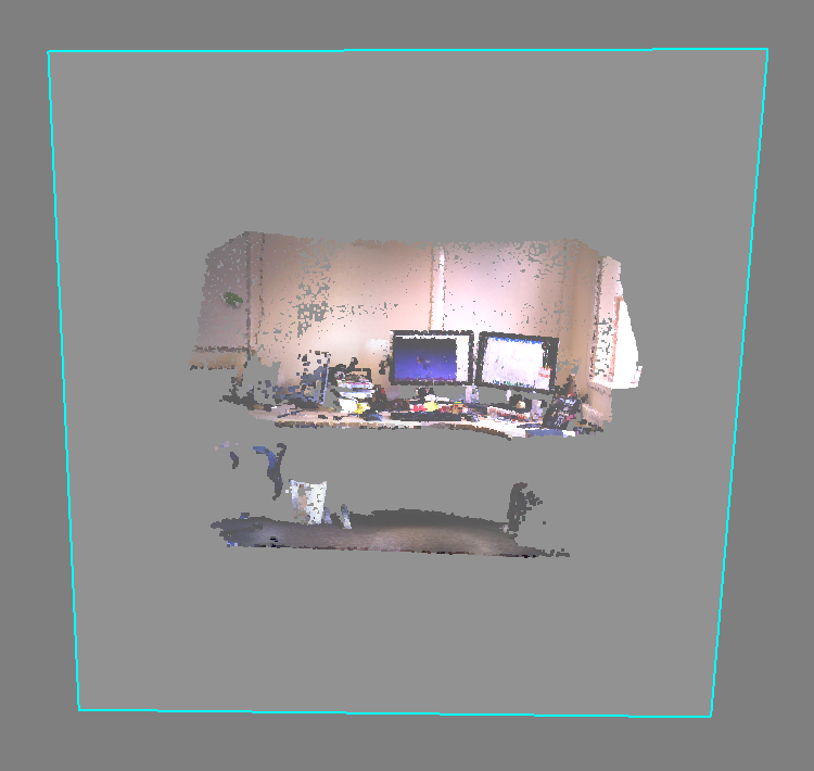
Your point clouds can be clipped with dynamic sections. To create a dynamic section, right-click on the parent Assembly of the point cloud and choose Create > Dynamic Section from the context menu.
Performance
The number of lights in a scene will not affect the rendering performance of the point cloud but it will affect the rendering of other scene geometry – imported CAD data. The points do not have normal information so can’t use the same lighting calculation as the rest of the scene. The point cloud will have “baked” lighting from the original scan. HDR and ambient occlusion have no visual effect on the point cloud.
Proper data preparation will have a big impact on point cloud performance. Excessive unnecessary detail should be eliminated if possible, a classic example of this is a very high concentration of points on the floor near each scan site. If you require 1mm point accuracy, then thinning the points before exporting them from the capture software will yield a high benefit.
Point size can also have a significant impact on performance. Each point is rendered as a world sized quad and the most attractive results are achieved by adjusting the point size so many the points overlap or nearly overlap which gives the appearance of a solid surface. If the points exhibit a high degree of non-uniformity in density the preferred point size may lead to large amounts of over draw in some areas, this over draw will have a strongly negative impact on performance.
In a collaborative or cluster setup the point cloud must be in a location accessible by all systems running Visionary Render or locally saved in the same location name. So, it can be stored on a network location accessible by all systems or stored locally on each system under the same filename and folder structure – e.g. C:\MypointClouds\demoroom.dat on the local drive, M:\MyPointClouds\demoroom.dat on a mapped network drive, or \\server\data\pointclouds\demoroom.dat as a UNC path.
Settings
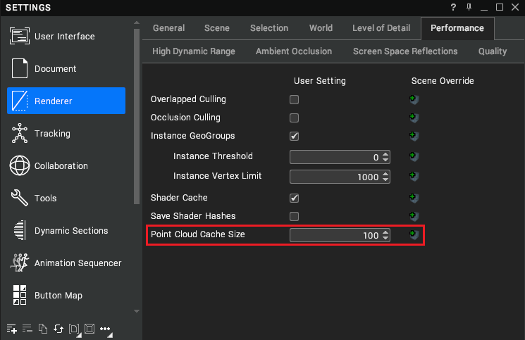
You can configure point cloud performance from the Settings window (F6) under Renderer > Performance.
| Setting | Description |
|---|---|
| Point Cloud Cache Size | The percentage of total computer memory to make available for caching point clouds. [default: 100%] |