Textures and Materials
Materials are used to change the visual appearance of assemblies within Visionary Render. They define the surface appearance of assemblies. They are made up of several different properties which when combined produce the material definition.
Images or texture maps can be used to further modify the appearance of the material to add realism to the scene.
Textures
Textures are images which can be loaded into Visionary Render and used in Materials to provide more realistic surface finishes. Textures can be generated from digital cameras, mobile phones, downloaded from the internet and from Libraries of textures available for free or purchased. Example textures are included in our resources download.
Supported File Formats
| Format | Extensions |
|---|---|
| Adobe Colour Table Files | act |
| Adobe Photoshop Files | psd |
| Bitmap Files | bmp |
| DirectDraw Surface Files | dds |
| Dr. Halo Files | cut |
| Graphics Interchange Format Files | gif |
| Homeworld Texture Files | lif |
| Interleaved Bitmap Files | lbm |
| JPEG Files | jpg, jpeg |
| JPEG 2000 Files | jp2 |
| JPEG Network Graphics Files | jng |
| JPEG XR Files | jxr |
| Kodak PhotoCD Files | pcd |
| Multi-PCX Files | dcx |
| OpenEXR Files | exr |
| PaintShop Pro Files | psp |
| Palette Files | pal |
| Portable Anymap Files | pnm |
| Portable Bitmap Files | pbm |
| Portable FloatMap Files | pfm |
| Portable Gray Map Files | pgm |
| Portable Network Graphics Files | png |
| Portable Pixel Map Files | ppm |
| Quake 2 Texture Files | wal |
| Radiance High Dynamic Files | hdr |
| Raw Data Files | raw |
| RGB Files | rgb, rgba, bw, int, inta |
| Silicon Graphics Files | sgi |
| Softimage PIC Files | pic |
| Tagged Image Files | tif |
| Truevision TARGA Files | tga |
| Virtalis Texture Files | vtx |
| WebP Files | webp |
| Windows Icon Files | ico |
| ZSoft PCX Files | pcx |
Compression Formats
Textures can be compressed so they take up less memory and disk space. They can be compressed individually or all selected textures. Visionary Render supports RGBA_DXT1 (compressed 8 bits per red, green and blue component using the DXT1 S3TC compression format).
| Format | Description |
|---|---|
| RGB8 | Simple 8 bits per red, green and blue component. |
| RGBA8 | Simple 8 bits per red, green,blue and transparent component. |
| RGBA_DXT1 | Compressed 8 bits per red, green and blue component using the DXT1 S3TC compression format. |
| RGBA_DXT5 | Compressed 8 bits per red, green, blue and transparent component using the DXT5 S3TC compression format. |
Create
Textures can be added in two ways. The easy method is to locate the texture you wish in windows explorer and to drag and drop it into the Visionary Render window. Once dropped, the texture will appear in the Developer tab under Libraries, DroppedFiles library and in the Browser. If dropped directly onto the Texture slot, it will appear in the Default Library.
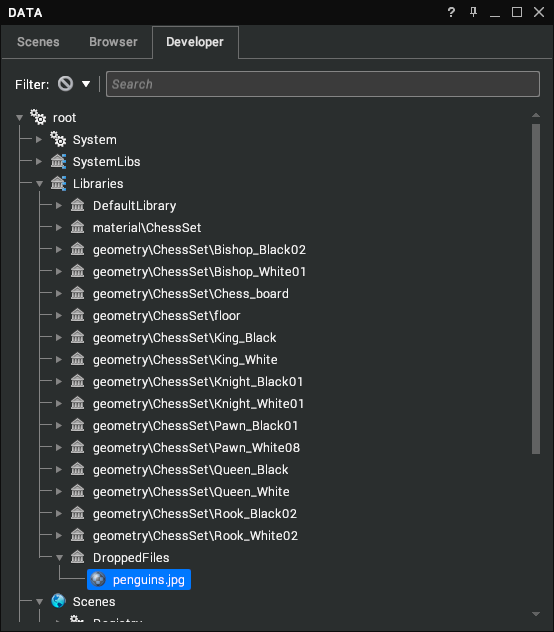
Textures can also be added in the Browser window by the Create Asset drop down or by Right Click, create texture and selecting the image from your pc. The Filter drop down will define what will be displayed when right clicking in the Browser.
The texture is now available to use in a material. To use the texture, drag and drop the texture into the appropriate map channel in the material properties window.
Select
Selecting textures applied to a material/assembly is accomplished in the same manner as selecting materials in the context menu. This will highlight the texture in either the Browser or the library tree if the Developer tab is open.
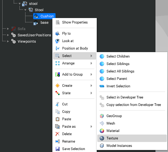
The secondary method picks the textures from the material itself. Select a material with textures and you will see in the properties window that one or more of the map channels contains a texture link. Clicking on this will open the texture properties.
Materials
A Material is used to describe the surface appearance of a Model. A material has a name, is normally contained within a Library, and are automatically generated when CAD data is imported.
In a Library parent node in Data window > Developer > Libraries you can:
- Create your own materials.
- Modify an existing material.
- Delete a material.
A material can be used across multiple Models within a scene. Models reference materials so if the material properties change all Models using it are updated.
Create
New materials can be created in either the Browser tab or in the Developer tab under Libraries in the tree. By right clicking in an open area of the material browser, you will have an option to create a new material. This menu is also available by selecting the Create Asset drop down.
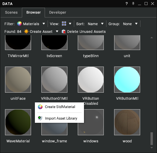
This method creates a new material in the Default Library Materials. In a scene with imported materials, these will appear under a specific Library associated with the imported data. If you wish to keep all materials in the same library, you can also create material by right clicking in the selected Library.
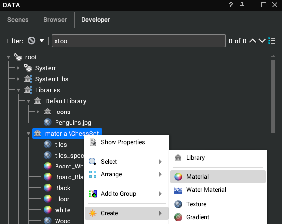
In both of these creation methods, the materials will be visible in the browser window no matter which library they are in. Best practice when creating any new node is to rename it as the Data window can easily become densely populated.
Select
There are two methods of selecting materials from Assemblies in a scene. The first is part of the standard context menu and can be accessed by right clicking a node in the Data window or on an item in the 3D viewport then select Select > Material.
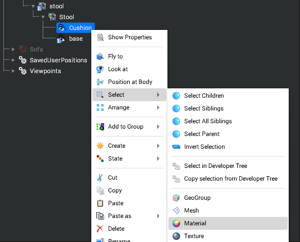
This will select the material of the assembly in either the Browser or the library tree if the Developer tab is open. If the Properties window is open, the selected material will also appear in there.
The second method is used within the 3D window. Holding down Shift + Ctrl whilst left clicking on an assembly will highlight the material in the Browser or the library tree if the Developer tab is open and, if open, the Properties window.
Browser
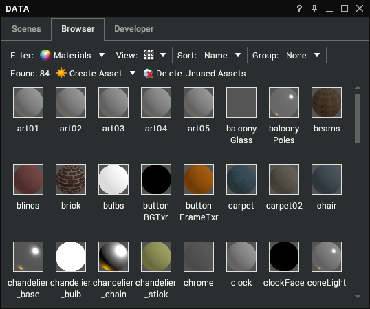
The material browser provides quick access to all the materials used in the loaded scene. They can be viewed as a list, small or large icon format. Large and small icon views provide a visual of the material as applied to a sphere assembly as well as the name of the material.
In list view, a number of details can be seen ranging from Diffuse colour to Opacity level, whether a texture is applied to how many Models the material is used on.
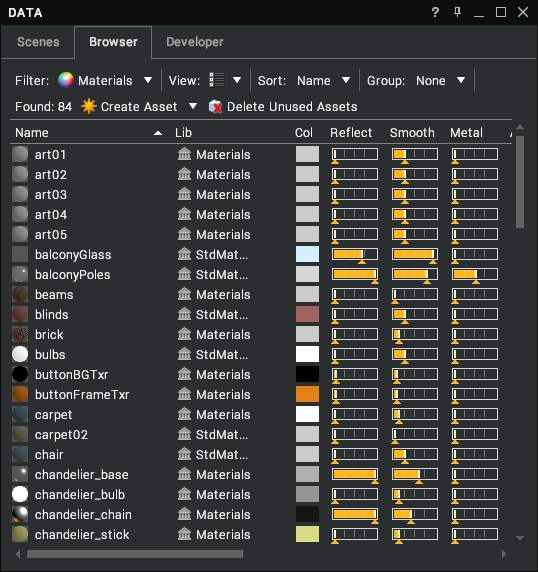
Materials can be sorted by any of the categories to aid in finding the desired material. In all three views, the material can be applied to an assembly in the scene by either:
- Drag and drop the material onto the scene assembly in the 3D window. If Alt is held down whilst dragging, this will apply the material to the GeoGroup rather than the entire object.
- With an assembly selected, right-click on the material and select Apply to Selected.
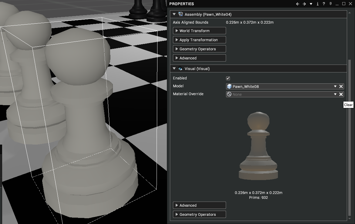
- With an assembly selected, drag and drop the material into the Material Override box in the visual properties window.
A fourth method allows you to drag a material from one assembly to another in the 3D scene by pressing the Alt key whilst left click and dragging between assemblies.
Whenever a material is applied, it Overrides the existing material but doesn’t replace it.
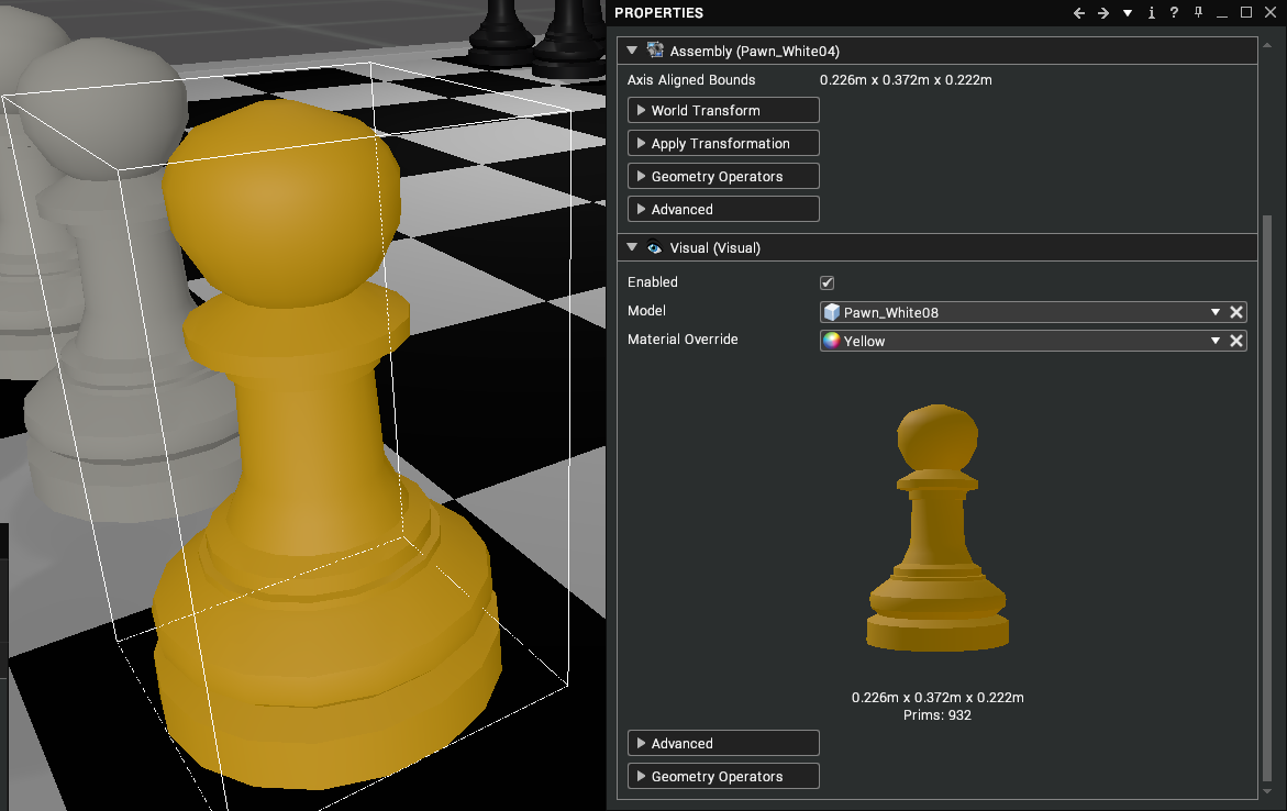
To revert the material to its original, select the Clear Link X.
Physically Based Materials
The Standard Material in Visionary Render is what is known in computer graphics as “physically-based”. Physically Based Materials attempt to describe a surface using a small number of intuitive physical properties; base colour, smoothness, reflectivity and metallicness.
The renderer uses these properties to physically simulate the way light is reflected, absorbed, and scattered by that surface. These are calculated whilst simultaneously enforcing the rule of energy conservation (the amount of light reflected or scattered cannot exceed the amount of light hitting the surface) and the Fresnel effect (a surface reflects more light at glancing angles to the viewer’s eye).
A material is defined using several properties:
- Colour (RGB)
- Reflectivity
- Smoothness
- Metallicness
- Ambient (The colour of an object where it is in shadow)
- Emissive (The colour of the emissive intensity)
- Emissive Intensity
- Opacity
- Textures – images used to affect the appearance
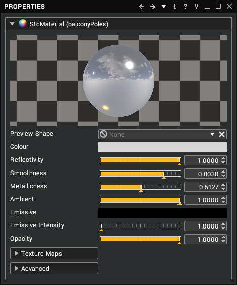
All Models have a material associated with them, a model without a material would not be visible in the viewport. Physically based materials require either an Environment Map or Skybox to truly work as they require an environment to reflect. The standard approach is to use a Skybox within the scene with material specific Environment maps detailed later.
Material Properties
Material properties are split into 3 sections: core material properties, texture maps, and advanced. The core properties enable you to create a simple material very rapidly whilst adding textures and using more advanced options can be used to create a more realistic material.
Colour
This property can be thought of as the overall colour of the surface. It represents how much of each wavelength of light is scattered and absorbed (or reflected if the material is a metal). If this were red then only red should be scattered while green and blue are absorbed, so it will tend to look red in colour (depending on the other physical parameters of the material).
Selecting the colour bar will open the colour wheel. RGB values can be typed into the three boxes or colours can be selected by clicking or dragging around the wheel and square. Note that colours range from 0-255 where 0,0,0 is black, 255,255,255 is white and 255,0,0 is red with any combination of values in between.
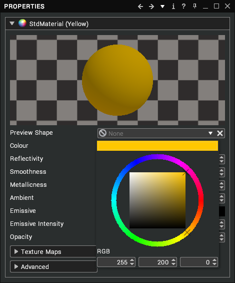
The colour picker describes the colour using the Hue, Satuation, Value (HSV) model. The circle describes the Hue and the square describes the Saturation and Value. As you alter these values all Models using this material will be updated immediately.
Reflectivity
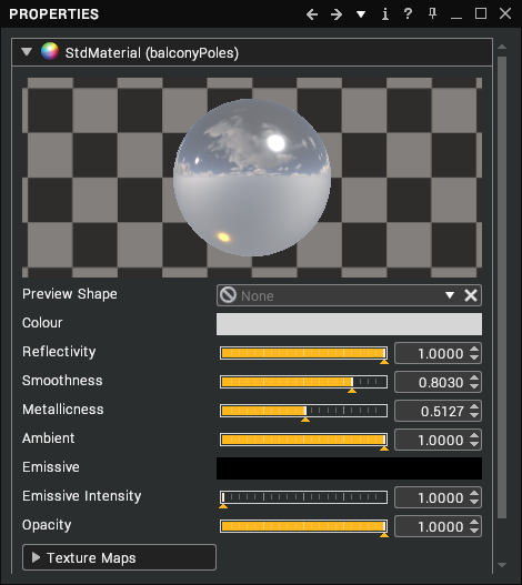
This property is the percentage of light that is reflected straight back at the light when the surface is directly facing the light, and inversely how much light is scattered instead. This represents the minimum amount of light that can be reflected.
The Fresnel effect will add to this, so at a glancing angle a surface will exhibit more reflectivity than this amount because of this effect. This can also be thought of as the weight between diffuse scattering and specular reflection – a 100% reflective surface will not contain any diffuse scattering and so will appear to ignore the colour property, whereas a 0% reflective surface will not contain any reflected light when directly facing the light and the colour property will have its strongest influence. In other words, a bright red 100% reflective surface will reflect the surrounding light source, whereas a bright red 0% reflective surface will appear bright red.
Smoothness
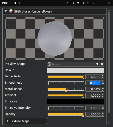
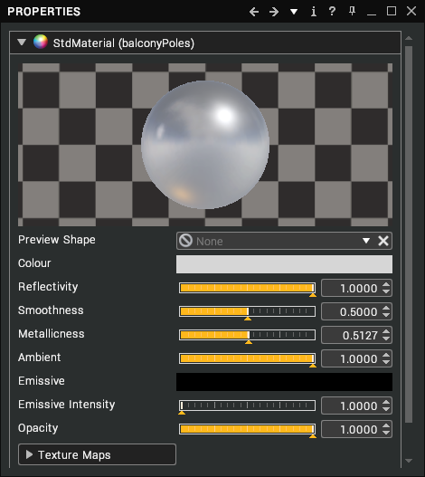
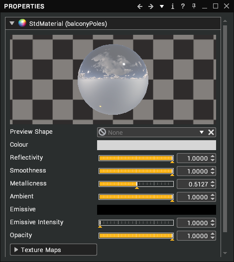
This property is literally how smooth or rough the surface is. This determines how sharp reflections from light sources and the environment are. A surface that is 100% smooth will reflect the incoming light perfectly, like a mirror, whereas a 0% smooth surface will only diffusely scatter the incoming light. For environment map reflections this means the reflected image goes from dull and very blurred (0% smoothness) to bright and pin sharp (100% smoothness).
Metallicness
There are different types of substances in real world. They can be classified in three main groups: Insulators (Dielectric materials), semi-conductors and conductors (Metallic materials). In general, we deal with dielectric and metallic.
Dielectric materials are the most common materials. Their optical properties rarely vary much over the visible spectrum: water, glass, skin, wood, hair, leather, plastic, stone, concrete, ruby, diamond etc.
Metals. Their optical properties vary over the visible spectrum: iron, aluminium, copper, gold, cobalt, nickel, silver etc.
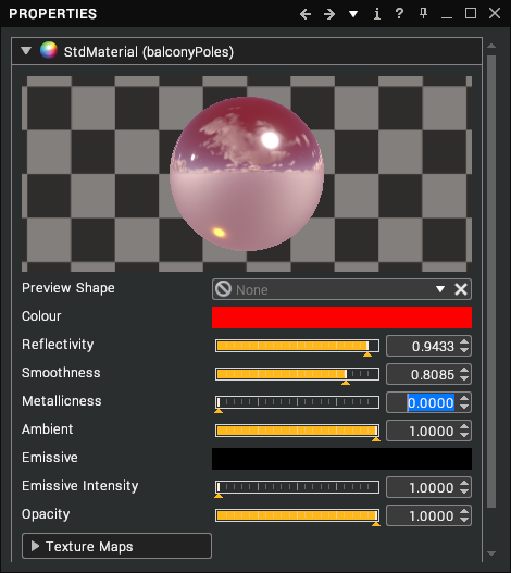
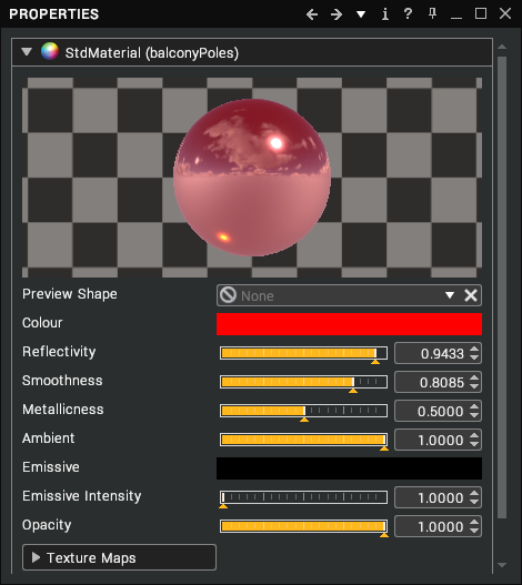
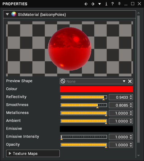
The main difference between a metal and a non-metal in the Visionary Render lighting system is a metal surface’s reflections are coloured by the colour property whereas a non-metal surface’s reflections are always coloured white. The other significant difference is that metals have no diffuse scattering, and so tend to only reflect and not absorb and scatter.
Ambient
This property is how much light from ambient lights is reflected. Because ambient lights have no direction this value will make the surface reflect the same percentage of ambient light in all directions. The Ambient property becomes especially useful when combined with an Ambient Map because it allows you to bake ambient occlusion into an assembly, which makes folds, creases, and crevices on the surface more apparent.
Emissive
These Emissive and Emissive Intensity properties together dictate what colour is emitted by the surface and how brightly that colour is emitted. Emission is independent to the lights and environment map. It allows the surface to simulate things like area lights or display screens. The emissive effect of a surface is most apparent when the HDR rendering mode is enabled, especially if the emissive intensity property is large - the surface will appear to glow.
Opacity
This property dictates how opaque the surface is. Anything less than 100% and surfaces behind this will be visible through it. The exact way this is handled is controlled by the blending property, which is automatically set to “None” when Opacity is 100% and 'Alpha Blend' for anything less than 100%.
The advanced properties add further control to opacity settings and will be covered later.
Texture Map Properties
Colour Map
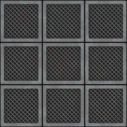
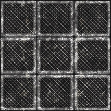
A colour map is a texture you use to define a surface's main colour. For example, if you want a metal grid in your scene, you can use an image of a metal grid as the colour map in the material applied to the assembly. When applying a colour map, you would normally adjust the base colour to white as the colour information is in the image.
Smoothness Map
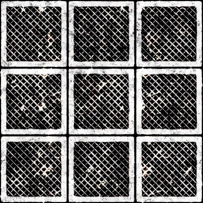
Shininess is often used in conjunction with a specular map. The smoothness level dictates the spread of the reflectivity, i.e. a snooker ball has a high reflectivity with a high smoothness value that creates a tight focused spot whereas brushed metal has a lower smoothness that diffuses the reflected highlight.
A smoothness map is only used when you have different levels of shine across a texture. In this case, you would have a colour, reflectivity, and smoothness map.
Reflectivity Map
Reflectivity maps are the maps you use to define a surface's shininess and highlight colour.
The higher the value of a pixel (from black to white), the shinier the surface will appear. Therefore, surfaces such as dry stone or cotton fabric would tend to have a very dark specular map, while surfaces like polished chrome or plastic would tend to have lighter specular maps.
Emissive Map
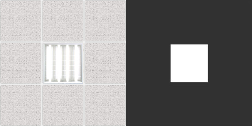
Emissive intensity and maps determine the amount an assembly is self-illuminated. Examples of this would be LED’s, fluorescent lights, or a computer screen. The emissive map is an image where black is no illumination through varying degrees to bright illumination at white. If a colour is used, then this will be the emitted colour.
Normal/Bump Map
Normal bump mapping is a technique that lets you simulate high-resolution surface detail on low-resolution polygonal models.
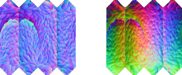
Object Space Normal Maps, are characterized by their full spectrum (rainbow-coloured) appearance. Object Space normal maps can be moved but the vertices of the mesh cannot deformed or the shading is wrong. Object space normals are best for things that can move, but not deform, like doors, cars, etc. Object Space maps use the Normal Map slot.
Tangent space normal maps are easily recognized by their mostly blue appearance. Tangent space normals almost always look bluish because normals in tangent space are always considered uv coordinates (0, 0, 1), even if in world space this is not true. The benefits of tangent space maps are the removal of the restrictions imposed Object Space normal maps. Tangent Space normal maps can rotate and deform, therefore they are ideal for characters or assemeblies that need to have vertex deformation. Tangent Space normal maps use the Bump Map slot.
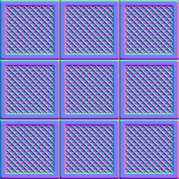
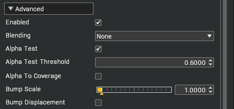
The advanced properties provide additional control over the effect scale. This will emphasise the depth of the bump but in general, the value should be around 1.
Reflection Map
A basic Reflection map creates the illusion of chrome, glass, or metal by applying a map to the geometry so that the image looks like a reflection on the surface. This can be a sphere or cubemap.
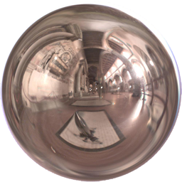
Cubemaps can be created in a tool such as AMD CubeMapGen.
Files should be saved as Cubemap DXT1 or Cubemap float32rgba if HDR. In a scene that uses a skybox, the reflection map defaults to using the skybox as reflection map. Adding a map to a material overrides this.
Opacity Map
There are 2 methods of creating opacity. The opacity map can be used which is a grey scale image where white is visible and black transparent. Anywhere in between will be translucent.
The second method uses the alpha or transparency of the colour map if it contains one. Image formats such as PNG or TGA can contain a transparency / alpha component. The advanced properties give further control on how the alpha/opacity is blended and also, allows to test for an alpha threshold level.
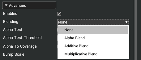
The threshold level determines at what point in an opacity map is it counted as transparent or not. Alpha To Coverage is a multisampling technique used in conjunction with Alpha Test to remove the need for alpha blending. It is more efficient than alpha blending but does not always look as good. MSAA must be enabled for this to work (this can be enabled from the Settings window under Renderer > General > Anti-aliasing).
Advanced Properties
Map Matrix
The map matrix provides control over how the textures are mapped onto a Model. The map matrix modifies the UV coordinates on Model the material is applied to. The UV coordinates describe what part of the texture to use on the Model. Whilst it doesn’t adjust the actual UV map for the Model, it allows you to move, rotate and scale that UV map to adjust texture direction, tiling, etc.
Offset is the position on the texture, with 0.0,0.0 being bottom left and 1.0,1.0 top right. This allows you to use the entire texture or a small part of it.
Scale is the number of repeats in the two directions. A value of 1.0,1.0 would display a single instance of the image. A value of 2.0,1.0 would display two copies of the texture across the assembly.
This image indicates the UV coordinates on a simple surface.
The following images demonstrate some simple settings for the Offset and Scale values.
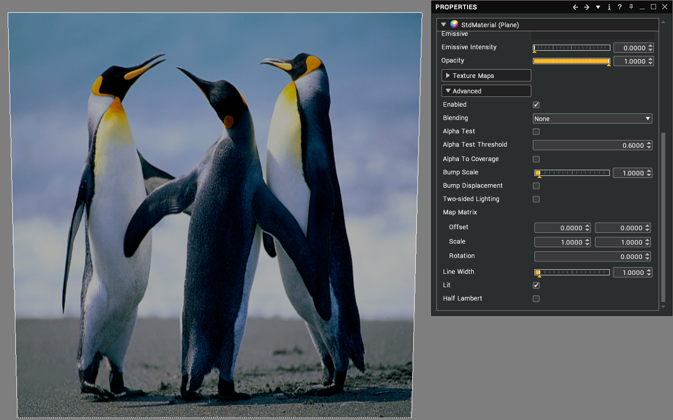
Simple default values.
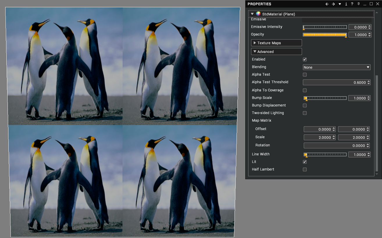
Scale of 2 by 2.
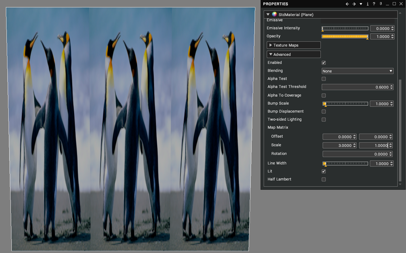
Scale of 3 by 1.
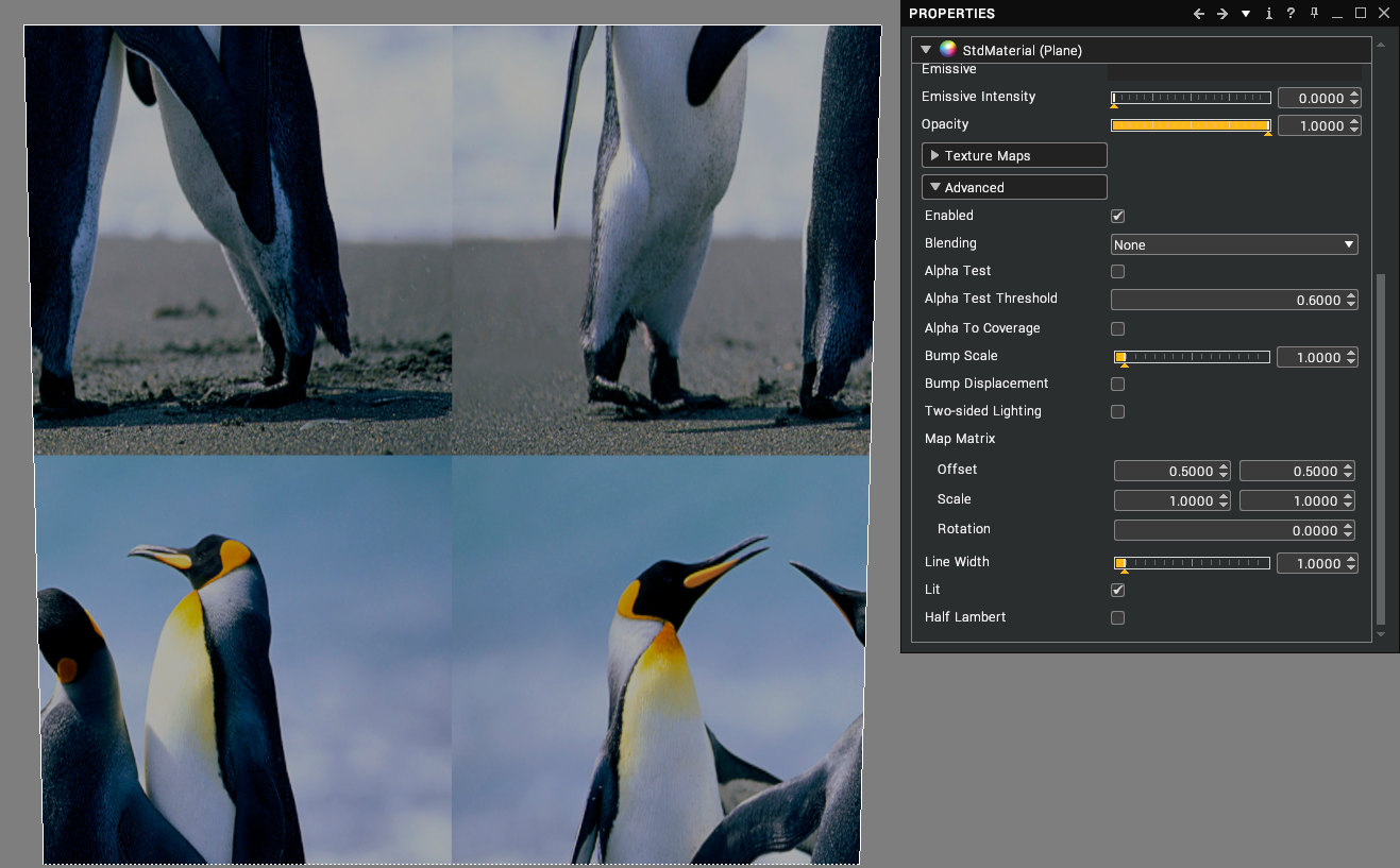
Offset of 0.5 by 0.5.
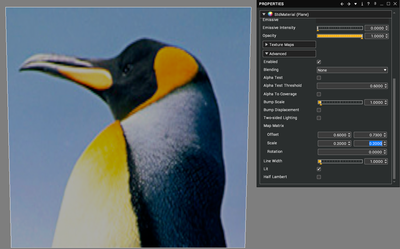
Combination of Scale and Offset to centre the Penguin head in the middle of the Cube.
Water Material
This special kind of material can be applied to objects in order to give them the appearance of water. For instance, it could be applied to a plane to create a swimming pool.
| Property | Description |
|---|---|
| Enabled | Render the ocean. [default: true] |
| Animated | Animate the ocean. [default: true] |
| Colour | The colour of the water. This colour is used in conjunction with the extinction distance and scattering amount to bias the final colour seen above and beneath the ocean. [default: black] |
| Sea State | The general condition of the ocean with respect to how rough the wind waves are. [default: 1.0] |
| Choppiness | The choppiness of the waves. [default: 3.0] |
| Patch Resolution | The number of vertices to use for one patch of water. [default: 128 x 128] |
| Patch Size | The area of a single patch of water in metres. [default: 1.0] |
| Extinction Distance | The distance in metres a ray of light has to travel through the water before it's almost entirely extinguished. For the clearest ocean waters on earth this value would be 150 metres. [range: 0.0 to 200.0; default: 50.0] |
| Scattering Amount | Scales the amount of light scattered towards the viewer due to particulate matter such as algae in the water. [range: 0.0 to 1.0; default: 0.11] |
| Depth Scale | Scales the calculated submerged depth of objects used by the underwater lighting model to attenuate light from above the ocean. This allows you to tweak the final effect if your scene isn't visible enough under realistic conditions. A value of 1.0 means no scale, therefore realistic depths are used. [range: 0.0001 to 4.0; default: 1.0] |
| Distance Scale | Scales the distances the underwater lighting model uses to calculate realistic fog effects. This allows you to tweak the final effect if your scene isn't visible enough under realistic conditions. A value of 1.0 means no scale, therefore realistic distances are used. [range: 0.0001 to 4.0; default: 1.0] |
| Reflectivity | How much incoming light should be reflected in the water when looking straight down on the surface. Note that there will always be some reflection as the surface becomes more edge-on towards the horizon because of the fresnel effect. [range: 0.0 to 1.0; default: 0.02] |
| Wind | The direction and intensity of the wind. [default: 1.0, 0.0, 1.0] |
| Wind Bias | How much the waves will appear to travel in the direction of the wind. 0 means they will move chaotically back and forth into and out of the wind. 1 means they will move very noticeably along the wind direction. [range: 0.0 to 1.0; default: 0.4] |
| Wind Lane Wave Amplitude | The heights of wind lane waves. [default: 0.0] |
| Wind Lane Wave Wavelength | The lengths of wind lane waves. [default: 100.0] |
| Wind Lane Wave Speed | The speed at which wind lane waves travel across the surface of the water. [default: 1.0] |
| Displacement Scale | Scales the geometric displacement of waves. This can be used to make the ocean surface completely flat but still retain the lighting of a 3D surface. [range: 0.0 to 1.0; default: 1.0] |
| UV Scale | Multiplier for the UV coordinates of the mesh this material is applied to before using them to sample the water data. [default: 1.0] |