Special Effects
Render To Texture
Visionary Render can render the scene to a texture to create special effects like mirrors. Right-click on a library node in the Developer tree and select Create > View/Tracking Nodes > Render To Texture from the context menu.
Properties
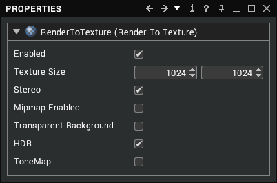
| Property | Description |
|---|---|
| Enabled | When enabled, the texture will be updated by the renderer. [default: true] |
| Texture Size | The size of the texture in pixels. [default: 1024 x 1024] |
| Stereo | Controls whether the texture is updated separately for the left and right eyes or only once per frame. [default: true] |
| Mipmap Enabled | Controls whether mipmaps are generated each time the texture is updated, to reduce visual artifacts when the texture is viewed at a distance. This can have a performance impact when enabled. [default: false] |
| Transparent Background | Makes the texture transparent where only the scene background or sky would be rendered. [default: false] |
| HDR | Uses a high dynamic range texture format to avoid clamping of brighter areas of the image; this is recommended when simulating a mirror but not a camera. [default: true] |
| ToneMap | Controls whether exposure adjustment, tone mapping and other effects from the High Dynamic Range settings are applied to the rendered image. [default: false] |
Example
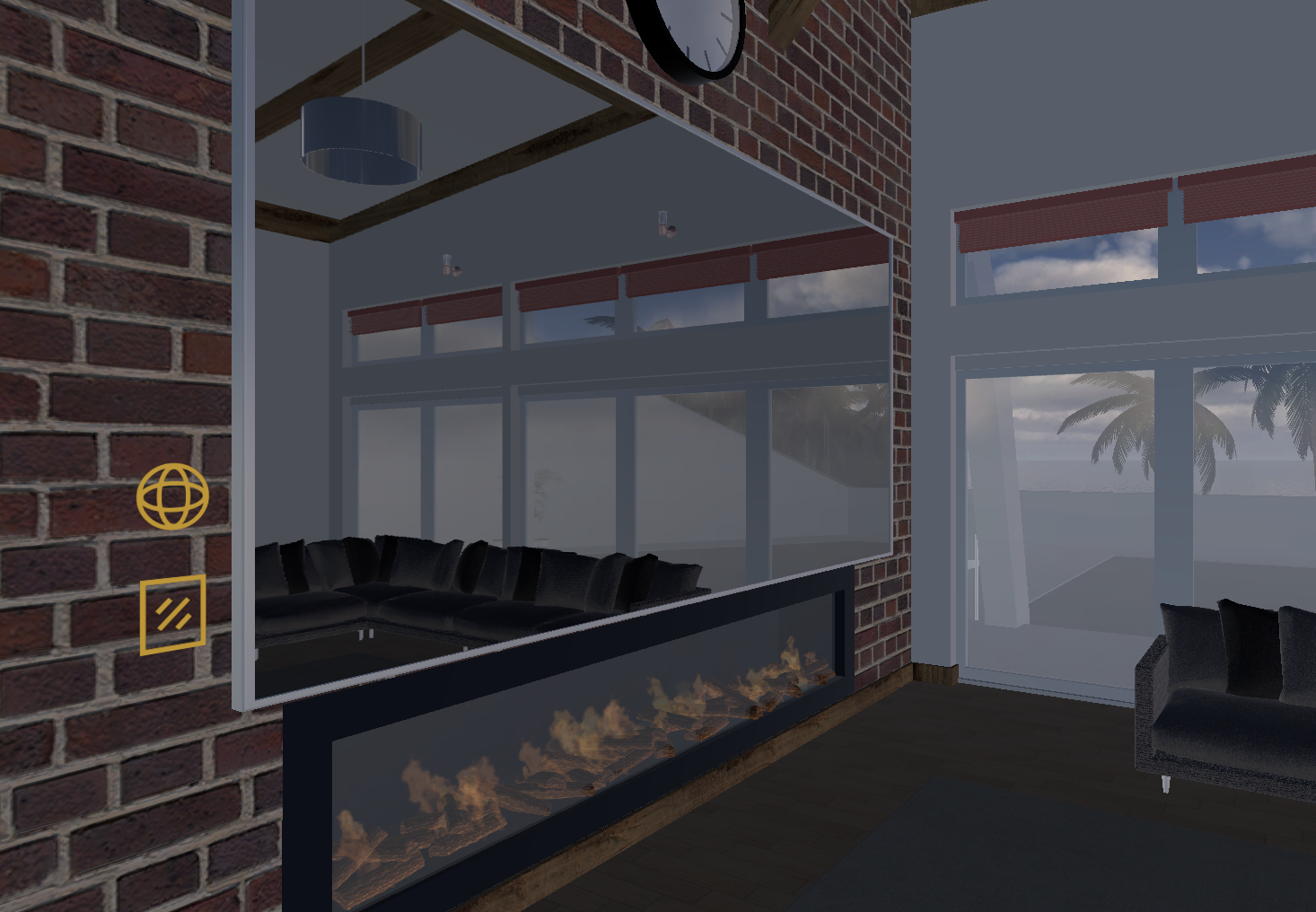
The image above shows a simple mirror effect. The mirror (central section surrounded by the purple frame) will reflect the view in front of it.
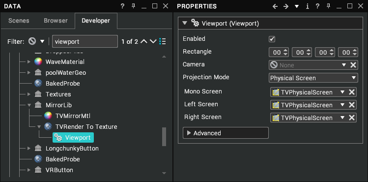
A PhysicalScreen is created and positioned within the scene – like any other assembly.
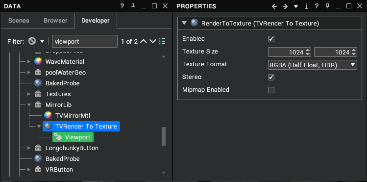
In the Library view a RenderToTexture assembly is created. The Texture size and format can then be set.
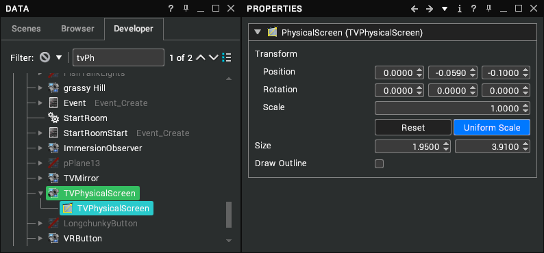
A viewport is created under the RenderToTexture. The Projection Mode is set to Physical Screen. The Mono, Left and Right properties are set to the previously created Physical screen in the Scenes view. This is done by dragging and dropping it from the Scenes view onto the property.
Now the RenderToTexture node can be used like a regular texture and can be inserted into any of the Map properties on a Material. To complete the creation of the mirror:
- Right-click on the parent assembly of the Physical Screen and select Create > Geometric Shape > Plane.
- Align the plane to the physical screen if necessary.
- Select the Plane and open its Material properties.
- Drag the RenderToTexture into the Colour Map property of the Plane’s material.
View Filters
View filters can be added to the scene to perform specific rendering effects to the final rendered image. There are several pre-configured filters built into Visionary Render.
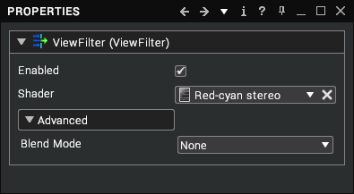
A View Filter is a node that can be created and placed anywhere in the scene tree that, if enabled, will perform post-processing on the final image drawn into the viewport. To do this, it uses a View Shader. A newly created View Filter uses the Default view shader, which applies edge detection to all the geometry in the scene. There are several pre-configured View Shaders built into Visionary Render.
View Shaders
A View Shader is an assembly that can be created and placed only under a Library assembly. When referenced by a View Filter it executes its shader source code on every pixel in the final image drawn in the viewport. You can view and edit this shader source code by double-clicking on the View Shader in the tree.
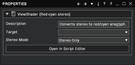
The View Shaders are written in the OpenGL Shading Language (GLSL). Please refer to the Visionary Render Programming Guide if you wish to create your own View Shaders. Otherwise, Visionary Render provides some built-in View Shaders for you to use in your scenes:
| Name | Description |
|---|---|
| Default | This is the default filter setting, which performs edge detection on the view. |
| Posterize | Quantizes the red, green, and blue components of the colour so they can be one of only 8 values, as opposed to being one of 256 values usually. This has the effect of looking like a poster printed using a very limited palette of ink. |
| Depth of Field | This adaptively blurs pixels depending on their distance from a focal plane. This distance is automatically set to be the distance of the pixel in the centre of the viewport, so anything drawn in the centre of the viewport will be sharp whereas everything else will be blurrier depending on how much closer or further away they are from this distance. This shader has a single tweakable parameter called “maxblur”, which dictates how large the blur kernel will be. |
| Camera Motion Blur | Adds motion blur to camera movement. Allows you to set the motion trail length, default is 2.0. |
| FXAA | Applies a fast, approximate anti-aliasing technique to reduce jagged edges. |
| Wobbly | Offsets the pixels horizontally in a wave pattern. |
| Show Normals | Shows the world-space normal vectors as colours around the mouse position. Allows you to set the radius from the cursor in pixels. |
| Torch | Places a point light 1cm above the surface under the mouse. The Distance and luminance can be set using the height and luminance metadata values. |
| Edge Detect | Simple Laplacian edge detect convolution. |
| White Edge | Detects Laplacian edges and draws them in white. |
| Red Edge Overlay | Detects Laplacian edges and draws them in red. |
| Sobel | Sobel operator. |
| Silhouette | Draws a white silhouette around geometry drawn against a clear background. |
| Stereo Deghost | Compensates for crosstalk between stereo 3D channels. |
| Red-cyan Stereo | Converts stereo to a red/cyan anaglyph. |
Multiple filters can be combined to create compound effects.
Surface Shaders
A surface shader is a chunk of code written in GLSL that is used to change the appearance of an Assembly in Visionary Render. The surface shader would be used in place of a Standard Material. GLSL is short for OpenGL Shading Language. The surface shaders are small programs which are run on the GPU (Graphics Processing Unit) on the graphics card.
See Surface Shaders in the Programming Guide for more information.
Deformable Meshes
Deformable Meshes (Morphs) allow the transformation of the vertices of one mesh to another mesh. Progressive morphs allow the specification of multiple morph targets to transition between. Skinning allows for the weighted surface of a mesh to transformed to a different position/orientation. Skinning uses linear interpolation.
There is currently no way of authoring skinned meshes in Visionary Render, however, skinning and morphing may be extracted from supported importers (FBX), or from Virtalis MaxExchange.
Usage
After importing a scene containing deformable meshes, they can be interacted with using the properties window.
- In the properties window (
Ctrl+P) if a visual is using a deformable mesh any controls such as morph target intensity will be listed. - Deformations occur in the order which they are presented in the tree.