Collisions
Visionary Render supports basic collision detection and response via the Character Controller, Collision node, and Detect Clashes context menu option.
Character Controller
The character controller can be enabled by clicking on the button in the Toolbar. It creates a capsule around your avatar to detect when it collides with the environment. This is enabled by default in the Start Room and is what permits you to walk around the room and up and down the stairs, etc. without walking through objects and walls.
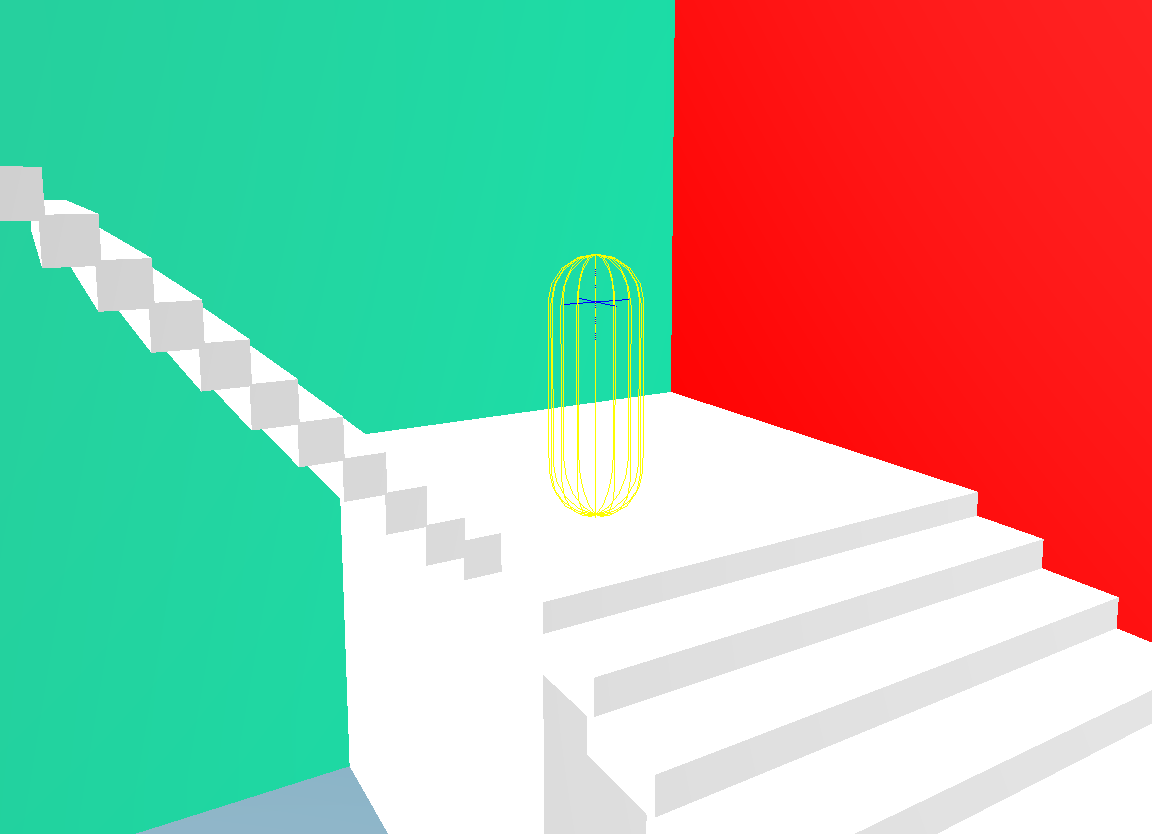
If the character controller is enabled whilst the camera is inside geometry, it will attempt to resolve the collision. If the collision cannot be resolved, a dialog will be shown. To fix the problem, disable the character controller, move the camera away from any geometry in the scene, and try again.
Settings
The character controller can be configured from the Settings window under User Interface > Navigation > Character Controller.
| Setting | Description |
|---|---|
| Character Controller Enabled | Whether to enable game character-style movement, with collision based on a capsule shape around the camera. [default: false] |
| Collision Enabled | Whether to enable wall collisions. If disabled, the camera will still follow the ground, but will be able to walk through walls. [default: true] |
| Collision Type | The collision group and mask for the character. The character will collide with objects for which both the character's collision group matches the object’s collision mask, and vice versa. [default: Custom] |
| Height | Total height of the capsule (including Hover Height). [default: 1.8] |
| Radius | Radius of the capsule. [default: 0.25] |
| Eye Offset | Y coordinate offset from the centre of the capsule shape to the camera position. [default: 0.45] |
| Hover Height | How high off the ground the character capsule shape hovers. Affects stair climbing. [default: 0.4] |
| Max Slope | Maximum incline the character can climb (degrees). [default: 30.0] |
| Gravity | Gravitational acceleration. [default: 9.81] |
| Terminal Velocity | Terminal fall speed. [default: 55.0] |
| Proxy Target | Node to control rather than the camera. [default: none] |
Collision Node�
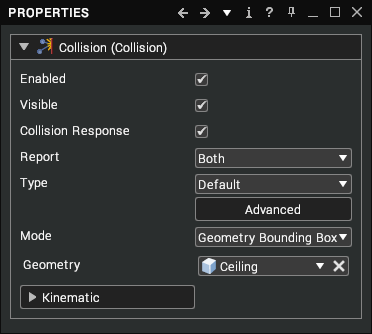
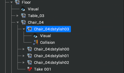
The collision node has several properties that determine how collisions are determined, what type of object it can collide with and which objects are informed of the collision. Right-click on the Assembly that you wish to add collision detection to and select Create > Collision from the context menu.
Properties
| Property | Description |
|---|---|
| Enabled | Whether or not the collision is enabled. |
| Visible | This can be used to debug collisions when there is unexpected behaviour. To show visuals, Settings > Collision > Debug Draw must also be enabled. |
| Collision Response | This property is linked to the dynamics and therefore only works with a dynamic license. It allows two objects to collide and trigger a collision without one object pushing the other. |
| Report | The objects that will be notified about the collision. This report is required to trigger touch/break scripts that are assigned to the parent or other scene objects.
|
| Type | This enables you to filter out certain types of object from triggering collisions.
|
| Mode | Mode is used to specify the collision geometry:
|
Kinematic
The Kinematic drop-down allows for a mass to be applied to an object so that it can have rudimentary physics applied to it. This requires a Dynamics feature license.
| Property | Description |
|---|---|
| Mass | Mass of the object. Set this to a value greater than zero to enable the object to act under dynamics. |
| Restitution | Coefficient of restitution. The ratio of the final to initial relative velocity between two objects after they collide. |
| Friction | Coefficient of friction. A value that shows the relationship between the force of friction between two objects and the normal reaction between the objects that are involved. |
Context Menu
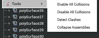
When collision nodes have been applied within a scene, they can be easily disabled or enabled using the context menu. Enabling or disabling will walk through the tree structure and enable/disable any collision nodes that are beneath it in the tree.
Detect Clashes
Often in scenes its useful to be able to detect whether parts can fit through gaps freely or whether they will collide with doorways, etc. Visionary Render provides a simple one-click method of adding this to a scene. Right-click on the Assembly that you wish to add collision detection to and select Tools > Detect Clashes from the context menu.
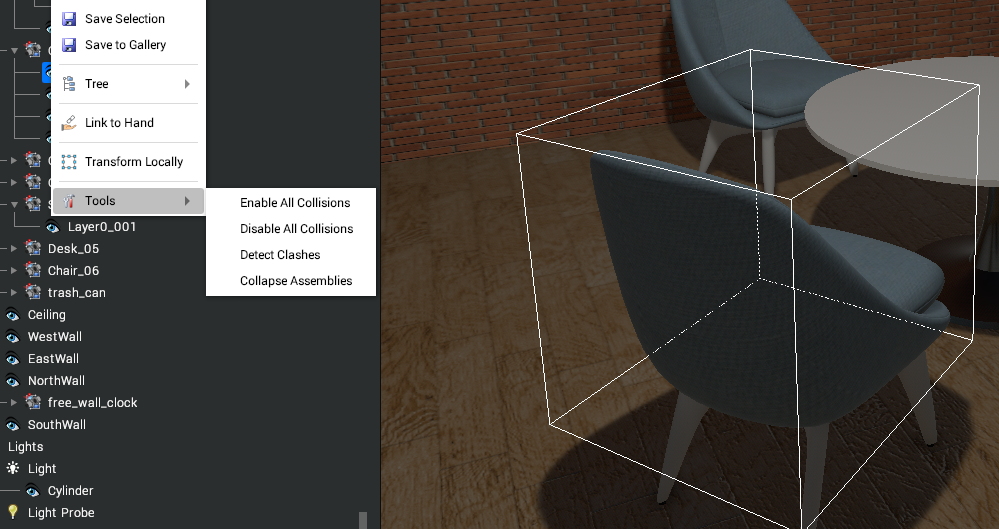
This will add a Collision node, Touch Script and Break Script to the Assembly and create a collision material called CLASH_assembly_name – i.e. CLASH_Solid_81.
When the part is moved, any object it collides with will be turned white whilst it is in contact. This colour can be changed as per changing any material colour.
The Detect Clashes script was modified in the 2023.1 release to handle simultaneous collisions and other edge cases. This change is not automatic for existing scenes so any Touch events created before this release should be updated to use tools.clashDetectionTouch(__Self, __Other, __Script). Any Break events should be updated to use tools.clashDetectionBreak(__Self, __Other).